Automotive Circuit
IMMOBILIZER
Published:2009/7/2 4:46:00 Author:May | From:SeekIC

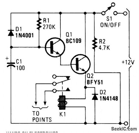
A flip of 51 puts the circuit into action. Power for the circuit is picked up from the ignition switch, and the circuit receives no power until the ignition switch is closed. When power is turned on, capacitor C1 is not charged and the emitter-follower Darlington pair (formed by Q1 and Q2) are cutoff, thus no power is applied to the relay (K1), which serves as Q1's emitter load. The relay's normally-open contacts are connected across the vehicle's points. (At this time, the relay contacts are open and have no effect on the ignition system). C1 charges by way of R1, causing the voltage at the base of Q1 to rise steadily. Thit creates a similar rise in the voltage at the emitter of Q2. A Darlington pair is used to provide a high input-impedance, buffer stage so that the voltage across C2 is free to rise almost to the full supply potential. Loading effects do not limit the charge potential to just a few volts. Eventually, the voltage applied to the relay becomes sufficient to activate it. The contacts close and short out the points. The ignition system now doesn't act properly and the vehicle is disabled. If the ignition is switched off, power is removed from the circuit and diode D1, which was previously reverse-biased, is now forward biased by the charge on C1. D1 allows C1 to rapidly discharge through R2 (and any other dc paths across the supply lines). The circuit is ready to operate when the ignition is again turned on. The engine will operate, but not for very long. The values of R1 and C1 provides a delay of about 25 to 30 seconds. Increase R1's value to provide a longer delay;
Reprinted Url Of This Article:
http://www.seekic.com/circuit_diagram/Automotive_Circuit/IMMOBILIZER.html
Print this Page | Comments | Reading(3)

Article Categories
power supply circuit
Amplifier Circuit
Basic Circuit
LED and Light Circuit
Sensor Circuit
Signal Processing
Electrical Equipment Circuit
Control Circuit
Remote Control Circuit
A/D-D/A Converter Circuit
Audio Circuit
Measuring and Test Circuit
Communication Circuit
Computer-Related Circuit
555 Circuit
Automotive Circuit
Repairing Circuit
Code: