Automotive Circuit
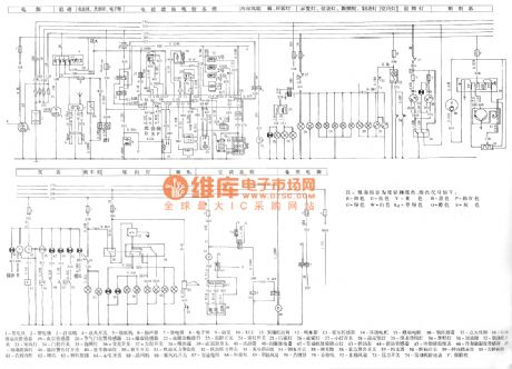
Meiri 3-Cylinder Engine Joint Electronic Control System Circuit
Published:2011/8/3 7:32:00 Author:Robert | Keyword: Meiri, 3-Cylinder, Engine, Joint, Electronic, Control, System | From:SeekIC

The picture shows the Meiri 3-cylinder engine joint electronic control system circuit.
In the circuit the part 1 is engine. The part 2 is battery. The part 3 is starting machine. The part 4 is ignition switch. The part 5 is speaker. The part 6 is cassette player. The part 7 is relay. The part 8 is electronic clock. The part 9 is oil pump. The part 10 is ECU. The part 11 is canister control valve. The part 12 is oil injector. The part 13 is hall sensor. The part 14 is stepper motor. The part 15 is thermistor. The part 16 is oxygen sensor. The part 17 is ignition coil. The part 18 is cooling fluid temperature sensor. The part 19 is vacuum sensor. The part 20 is throttle position sensor. The 21 is knock sensor. The part 22 is fault diagnosis interface. The part 23 is temperature control switch. The part 24 is fog lamp switch. And so on.
Reprinted Url Of This Article:
http://www.seekic.com/circuit_diagram/Automotive_Circuit/Meiri_3_Cylinder_Engine_Joint_Electronic_Control_System_Circuit.html
Print this Page | Comments | Reading(3)

Article Categories
power supply circuit
Amplifier Circuit
Basic Circuit
LED and Light Circuit
Sensor Circuit
Signal Processing
Electrical Equipment Circuit
Control Circuit
Remote Control Circuit
A/D-D/A Converter Circuit
Audio Circuit
Measuring and Test Circuit
Communication Circuit
Computer-Related Circuit
555 Circuit
Automotive Circuit
Repairing Circuit
Code: