
Circuit Diagram
Index 383
Common-mode voltage reaches + 1000V Differential amplifier circuit with INA110
Published:2011/8/30 2:48:00 Author:Jessie | Keyword: Common-mode voltage, Differential amplifier

As shown in figure, the circuitis common-mode differential amplifying circuit with the input voltagebeing+ 1000V. This circuit adopts mosfet (FET) input apparatus using amplifierINA110 and input resistance bleeder. Reverse phase input and in-phase input is respectivelycomposedof R1, R2 and R3, R4.Because R1=R3, R2=R4, the attenuation ratio of voltage divider is: K=R2/(R1+R2)=10/(10+990)=1/100. (View)
View full Circuit Diagram | Comments | Reading(1289)
Driver 50 Ω load linear amplifier circuit
Published:2011/8/30 2:45:00 Author:Jessie | Keyword: Driver 50 Ω load, linear amplifier

As shown in the chart, the circuitis the driver 50 Ω load linear amplifier circuit. This circuit consists of two components. The former stage is composedof thechip MC3401 and affiliated circuit, and the laststage is the OTL complementary symmetry power amplifier circuit. R2 is introduced tovoltage parallel negative feedback to improve the dynamic index. (View)
View full Circuit Diagram | Comments | Reading(845)
Homemade multi-functional thyristor charger circuit
Published:2011/11/13 21:02:00 Author:May | Keyword: Homemade, multi-functional, thyristor, charger circuit

Working principleThis set mainly consists of major loop and conttrol loop. The circuit is shown in diagram 5-14.(1)major loop part (charge loop part)Commercial power 220V passes transformer T1 and reduction voltage. Secondary major loop winding have five taps. Among them, S2-1 charges to 6V storage battery, S2-2 charges to 12V storage battery or charges to 6V storage with heavy current, S2-3 charges to 18V storage battery or chareges to 12V storage battery with heavy current, S2-4 charges to 24V storage battery.This voltage is controlled and output by thyristor. The output end connectsto fly-wheel diode VD5 and filter inductance L.(2) control loop partTransformer's secondary control loop winding can output 23V voltage. (View)
View full Circuit Diagram | Comments | Reading(1510)
Operational amplifier precision zero circuit (REF200) diagram
Published:2011/8/30 2:36:00 Author:Jessie | Keyword: Operational amplifier, zero circuit

As shown in figure, the circuitis operational amplifier precision zero circuit. In some applications, it requires the disorder voltage of amplifierbeing small, and when the power supply voltage changes, thedisorder voltage is not affected. As shown in figure (a), the circuitcan realize this function. The circuit adopts double current source integrated chip REF200.The internal structure and pin arrangement of the chipare shown in figure (b). (View)
View full Circuit Diagram | Comments | Reading(1360)
Low distortion AGC amplifier (AD824) diagram
Published:2011/8/30 2:31:00 Author:Jessie | Keyword: Low distortion, AGC amplifier

In communications, control and remote sensing system, the low distortion automatic gain control circuit is needed. As shown in diagram, the circuit is the low-distortion AGC amplifier. A1 is the amplifier. A2 is the voltage following device, which is used asisolation level to introduce feedback for amplifier A1. Integrated amp in (A) can be proper selected according to actual needs. If you hope the single power supply, you can choose low powerfour operational amplifiercircuit AD824A or AD824B; If you hope to adopt double power supply, you can use μPC4074 four operational amplifier integrated chip. (View)
View full Circuit Diagram | Comments | Reading(1639)
Intelligent pulse electric bicycle charger principle diagram
Published:2011/11/13 20:48:00 Author:May | Keyword: Intelligent pulse, electric bicycle, charger

Voltage driving type pulse width modulator
1. feature and function of TL494
TL494 is produced by the United States IR company. It is voltage driving type pulse width modulator, which can be used as switching power circuit in display, computer and other system circuit. The output triode of TL494 can connect to the mode of common emitter or emitter follower. So it can choose the double-end push-pull or single-end output mode. When ituses push-pull output mode, the differ of two drive pulse is 180°, but when it is single end mode, its two ways ofdrive pulse have the same frequency and same phase.
The internal function diagram of TL494 is shown in the following diagram
1IN+, 1IN-, 2IN+, 1IN input; FEEDBACK feed-back; DTC non load control; CT timing capacitor; RT timing resistor; GND ground; C1, C2 collector 1, 2; E1, E2 emitter 1, 2; Vcc power supply; OUTPUT CTR output control; REF reference.
2, application circuit
(View)
View full Circuit Diagram | Comments | Reading(3521)
Based on SPI bus high precision pressure testing system circuit
Published:2011/8/31 1:55:00 Author:Jessie | Keyword: SPI bus, pressure testing system

Using MAX1457, 27C64 each one piece,and matching a piezoresistive pressure sensor will constitute a pressure measurement module.N pieces ofpressure measurement modules and microcomputers, digital voltmeters canform the bus high precision pressure testing system based on SPI . The circuit is shown in diagram. It is a testing system composedof 6 transmissions, including two power lines, a simulation voltage output line, and three SPI interface lines. In addition, the multi-channel switch choosesmeasuring module andread-only memory through the MCS, ECS lines respectively. (View)
View full Circuit Diagram | Comments | Reading(656)
Electric bicycle intelligent charger using UC3845
Published:2011/11/10 2:55:00 Author:May | Keyword: Electric bicycle, intelligent charger

UC3845 is high-performance, single-end output current-mode PWM control circuit. Its biggest advantagesare fewer external components without independent auxiliary power supply, and simple external circuit assembly and low cost. Electric fly-back controllingbike uses it assmart charger, whichis very competitive in the market. The whole circuit principle is shown in Figure 1. Figure 2 is an internal block diagram of UC3845. Each pin function of UC3845 is shown in Table 1. The novelty of the circuit is that it does not use internal error amplifier IC1 (reasonably, pin 2 is the namely reversed end and itshould be grounded), but it directly uses second precision voltage regulator IC3 AS431for adjusting and controlling. In the following diagram, we will try to interview it. (View)
View full Circuit Diagram | Comments | Reading(10189)
Sail automatic transmission circuit diagram
Published:2011/8/29 21:23:00 Author:Jessie | Keyword: Sail automatic transmission


K85-automatic transmission electronic control unit (806 ~ 855), F5-fuse (10A, 857), S104-force low-end switch (847), S105-snow mode switch (851 ~ 855), S106-switch / process, economic / Power (844), S84-gear contact switch (857), Y47-unlock solenoid valve (857), E21-transmission mode indicator (on the shift lever, 858 - 860). (View)
View full Circuit Diagram | Comments | Reading(965)
Saiou ABS circuit diagram
Published:2011/8/29 21:15:00 Author:Jessie | Keyword: Saiou ABS

U4-ABS electronic control unit (707 ~ 748), P17-left front wheel speed sensor (715), P18-right front wheel speed sensor (724), F22-fuse (10A, 754), P19-left rear wheel speed sensor (735 ), P20-right rear wheel speed sensor (743). (View)
View full Circuit Diagram | Comments | Reading(830)
6z4 Tube amp circuit
Published:2011/8/29 20:56:00 Author:Jessie | Keyword: Tube amp


Voltage amplifier tube canreplace 6N1, thenR4 reduces to100kΩ, R10 reduces to50kΩ. 6Z4 can replace power rectifier electronic diode. Because single 6Z4'smaximumDC output current is only 75mA,it should use two tubes connected in parallel. It also can use semiconductor diode to replace it. (View)
View full Circuit Diagram | Comments | Reading(5075)
M6 car anti-lock braking system ABS traction control system TCS circuit
Published:2011/8/29 22:53:00 Author:Jessie | Keyword: ant-ilock braking system ABS, traction control system TCS


View full Circuit Diagram | Comments | Reading(1400)
Shaalis 2000 automatic transmission circuit diagram
Published:2011/8/29 22:52:00 Author:Jessie | Keyword: Shaalis , automatic transmission

View full Circuit Diagram | Comments | Reading(1124)
Siena ABS circuit diagram
Published:2011/8/29 22:51:00 Author:Jessie | Keyword: Siena ABS

View full Circuit Diagram | Comments | Reading(609)
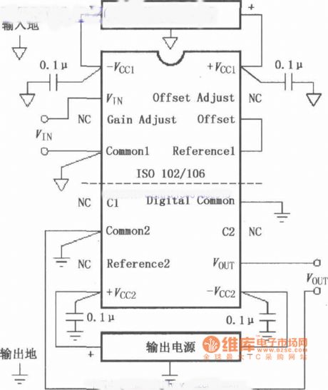
The basic connected circuit of signal of ISO102/106 and power supply
Published:2011/8/30 1:38:00 Author:Jessie | Keyword: connected circuit , signal, power supply
View full Circuit Diagram | Comments | Reading(652)
Emergency light using 6V battery cell automatic charger circuit 2
Published:2011/11/13 20:40:00 Author:May | Keyword: Emergency light, 6V, battery cell, automatic, charger

If it works forlong hours, its fever is serious, and it is easily to be destroyed. It is easily tolead to over-charge to cause the prematurely dry of electrolyte and shorting the battery life. For the shortcomings, the author changes it to auto-charger. After using six months, it works well. The circuit is shown in the above diagram.
Principle outline
It offers reference voltage for the base of T1. Relay J can achieve self-locking and automatic power off. When it is connected to the battery, K is pressed, power indicator L is lit, meanwhile J is energized and pulled in, K is self-locked by its contact J-0, and charging is starting. At this time, battery cell is under electrical, so T1 emitter voltage is less than (7.5V +0.65 V), T1 is cut off, T2 is also cut off, and this has no effect on the T3. When the battery voltage is charged to 7.5V, Tl emitter voltage is 7.5V +0.65 V, T1 is saturated and broken over, T2 is also broken over, T3 is cut off because its base voltage is dropped down, J is lost power and release, J-0 is cut, charging is stopped. Indicator light L goes out. It can charge to different voltage battery by adjusting W. (View)
View full Circuit Diagram | Comments | Reading(2344)
The circuit of technology in ISO102/106 dealing with analog and digital common terminal
Published:2011/8/30 1:37:00 Author:Jessie | Keyword: analog common terminal, digital common terminal

View full Circuit Diagram | Comments | Reading(962)
Unipolarity isolation test instrumentation amplification circuit composed of ISO100 with detuning adjustment
Published:2011/8/30 1:36:00 Author:Jessie | Keyword: Unipolarity isolation , test instrumentation amplification, detuning adjustment

View full Circuit Diagram | Comments | Reading(683)
Gree ZGP series computer control electronic disinfection cabinet circuit
Published:2011/8/30 1:35:00 Author:Jessie | Keyword: Gree ZGP series , computer control, electronic disinfection cabinet

View full Circuit Diagram | Comments | Reading(838)
555 vehicle turn signal electronic flasher circuit
Published:2011/11/10 2:58:00 Author:May | Keyword: 555, vehicle turn signal, electronic flasher
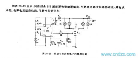
As shown in diagram 20-15,the flasherconsists of 555 oscilator and driver. Comparing with thermorelay scintillator, its advantagesinclude: low cost, strong power supply voltage suitability, high reliability, etc.
555 and R1, R2, C1 make up astable multivibrator, its oscillating frequency is about 1HZ. It adopts VMOS K75 tube as driving switch. When car turns left or right, it can break overto lightthe left or right indicator. (View)
View full Circuit Diagram | Comments | Reading(4099)
| Pages:383/2234 At 20381382383384385386387388389390391392393394395396397398399400Under 20 |
Circuit Categories
power supply circuit
Amplifier Circuit
Basic Circuit
LED and Light Circuit
Sensor Circuit
Signal Processing
Electrical Equipment Circuit
Control Circuit
Remote Control Circuit
A/D-D/A Converter Circuit
Audio Circuit
Measuring and Test Circuit
Communication Circuit
Computer-Related Circuit
555 Circuit
Automotive Circuit
Repairing Circuit