
Circuit Diagram
Index 392
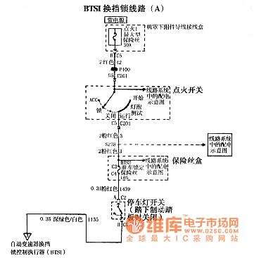
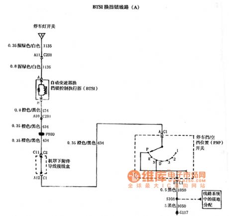
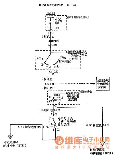
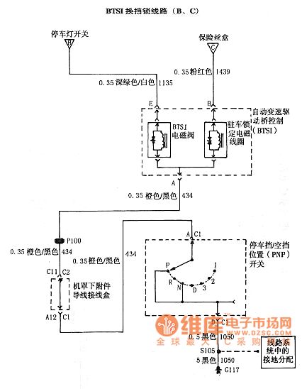
SGM Regal 2.0 L automatic transmission circuit diagram
Published:2011/8/24 2:41:00 Author:Jessie | Keyword: SGM Regal , 2.0 L automatic transmission
View full Circuit Diagram | Comments | Reading(719)
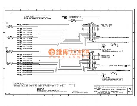
875p computer motherboard circuit diagram 039
Published:2011/11/22 21:17:00 Author:Ecco | Keyword: computer motherboard
View full Circuit Diagram | Comments | Reading(3066)
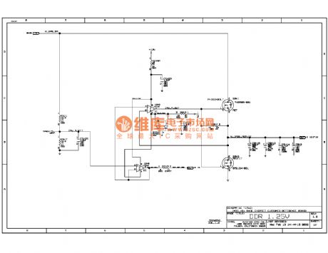
845E computer motherboard circuit diagram 57
Published:2011/11/22 21:18:00 Author:Ecco | Keyword: computer motherboard
View full Circuit Diagram | Comments | Reading(2207)
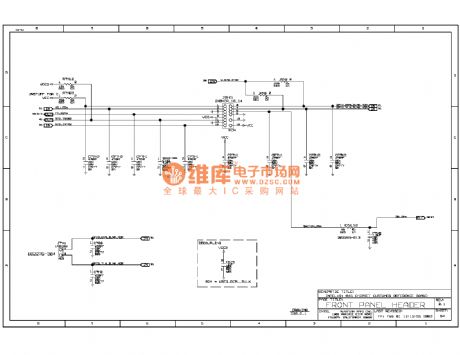
845ddr computer motherboard circuit diagram 54
Published:2011/11/22 21:17:00 Author:Ecco | Keyword: computer motherboard
View full Circuit Diagram | Comments | Reading(1867)
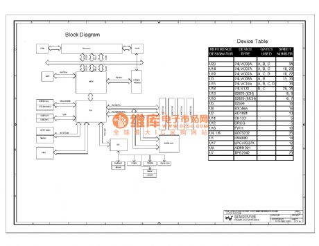
820e computer motherboard circuit diagram 02
Published:2011/11/10 3:04:00 Author:Ecco | Keyword: computer motherboard
View full Circuit Diagram | Comments | Reading(2191)
The monostable multivibrator
Published:2011/11/22 21:52:00 Author:Ecco | Keyword: Monostable multivibrator

View full Circuit Diagram | Comments | Reading(874)
Car headlight -HID lighting igniter
Published:2011/12/8 1:19:00 Author:Ecco | Keyword: Car headlight, HID lighting igniter

View full Circuit Diagram | Comments | Reading(2322)
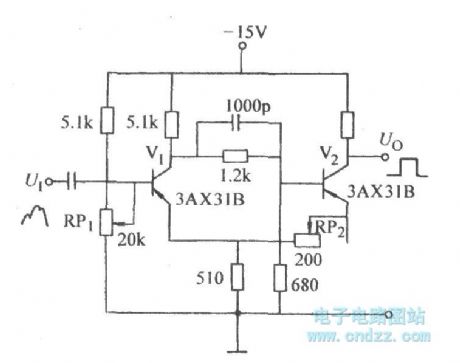
Emitter-coupled bistable circuit for improving sensitivity
Published:2011/10/18 22:00:00 Author:Ecco | Keyword: Emitter-coupled bistable , improving sensitivity
View full Circuit Diagram | Comments | Reading(679)
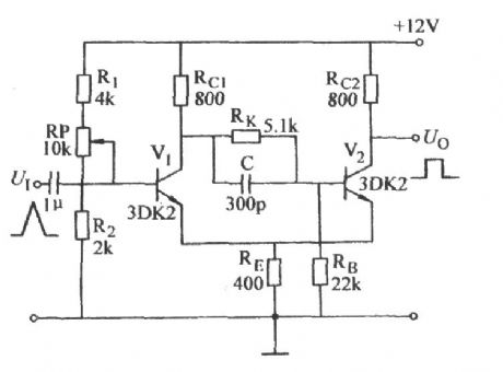
Emitter-coupled bistable circuit with changable action of circuit
Published:2011/10/18 21:57:00 Author:Ecco | Keyword: Emitter-coupled bistable , changingable action
View full Circuit Diagram | Comments | Reading(967)
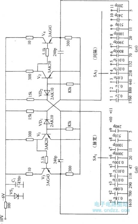
Astable circuit with sub-file adjusting pulse width
Published:2011/10/18 22:06:00 Author:Ecco | Keyword: Astable circuit , sub-file adjusting , pulse width
View full Circuit Diagram | Comments | Reading(591)
Sound control color light circuit 555, KD-5602 with twitter
Published:2011/12/8 1:04:00 Author:Ecco | Keyword: 555, Sound control, color light , twitter
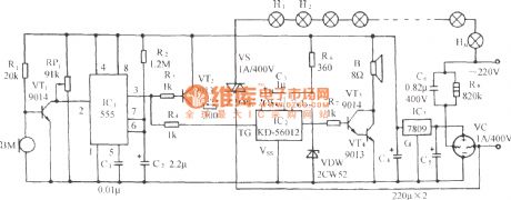
The circuit is shown as the chart. It consists of acoustic / electric sensors , trigger timing circuit , thyristor trigger control circuit , twitter circuit andAC buck rectifier circuit.
(View)
View full Circuit Diagram | Comments | Reading(1022)
Sound control color light circuit with twitter( 555, KD-5602 )
Published:2011/12/8 1:05:00 Author:Ecco | Keyword: 555, Sound control, color light, twitter

The circuit is shown as the chart. It consists of acoustic / electric sensors , trigger timing circuit , thyristor trigger control circuit , twitter circuit andAC buck rectifier circuit.
(View)
View full Circuit Diagram | Comments | Reading(1021)
The winding tap T- connection three-speed circuit of single-phase motor
Published:2011/12/7 20:51:00 Author:Ecco | Keyword: winding tap , T- connection , three-speed , single-phase motor

View full Circuit Diagram | Comments | Reading(2595)
The winding tap L-2 connection three-speed circuit of single-phase motor
Published:2011/12/7 20:53:00 Author:Ecco | Keyword: winding tap , connection , three-speed circuit , single-phase motor

View full Circuit Diagram | Comments | Reading(3620)
Ultrasonic remote control switching circuit diagram
Published:2011/9/16 1:04:00 Author:Rebekka | Keyword: Ultrasonic remote control, switching circuit
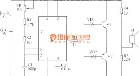

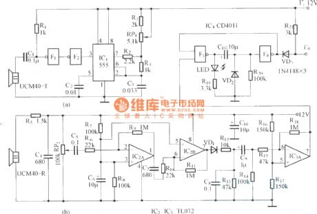
This example describes the ultrasonic remote control switch. The remote distance is 10m or more. It can be widely used in industrial automation control and home appliance control. The ultrasonic remote control switching circuit is composed of an ultrasonic transmitter circuit and receiver circuit. Ultrasonic transmitter circuit is composed of the control button S, time-base integrated circuit IC1, transistors V1, V2, resistors R1 ~ R5, potentiometer RP1, diode VD1, VD2, capacitors C1, C2 and the first ultrasonic transmitter composed of B1. Here is the circuit.
Ultrasonic transmitter circuit
Ultrasonic receiver circuit is composed of an ultrasonic receiver B2, transistors V3 ~ V5, operational amplifier integrated circuit IC2, relay K, the diode VD3 ~ VD5 and resistors R6 ~ R15, capacitors C3 ~ C5, potentiometers RP2 and other components. Here is the circuit.
Ultrasonic receiver circuit.
Optional components selectionR1 ~ R15 use 1/4W carbon film resistors or metal film resistors. RP1 and RP2 use small potentiometers or sealed variable resistors. C1 uses high-frequency ceramic capacitors; C2 ~ C5 use monolithic capacitors or polyester capacitors.VD1 ~ VD5 use 1N4148 silicon switching diodes. V1, V3 and V4 use S9014 silicon NPN transistors; V2 and V5 use S9015 silicon PNP transistors; V6 uses S9013 or C8050 silicon NPN transistor. IC1 uses NE555 or 5G1555 time-base circuit; IC2 uses μA741 or CA3140, LF351 etc. integrated circuits. B1 uses T40 ultrasonic transmitter emission terminal; 82 uses R40 ultrasonic receiver terminal. K uses universal 9V DC relay,andthe capacity of visual contact may be controlled by electrical power.
(View)
View full Circuit Diagram | Comments | Reading(2586)
The structure of ultrasonic sensor
Published:2011/9/16 0:58:00 Author:Rebekka | Keyword: structure, ultrasonic sensor

View full Circuit Diagram | Comments | Reading(1025)
Ultrasonic guard against theft alarm detector
Published:2011/9/15 2:21:00 Author:Rebekka | Keyword: Ultrasonic guard against theft alarm
View full Circuit Diagram | Comments | Reading(1677)
6Y7 Monolithic automatic voltmeter
Published:2011/9/15 21:16:00 Author:Rebekka | Keyword: Monolithic automatic voltmeter
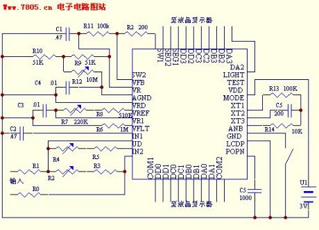
Overview:1. Low power consumption: We hope two ordinary button battery can be used for half an year.2. Low voltage: It does not use bulky batteries such as 5 # battery or tandem structure.3. High precision: It owns 31/2 or more precision.4. High stability: It requires a good reading stability.5. Low-cost: The cost of chip is lower than RMB10.00.6. Automatic: Fool-type operation.7. Monolithic: It does not use other active devices such as reference power and thermistor etc.That is these requirements produce the following design requirements.1. Use ordinary digital circuits manufacturing chip.2. Precision reference supply.3. Precision comparator.4. Precision Rectifier.5. 3V power supply.6. Working current is lower than 1MA.7. Analog / digital conversion.8. The least amount of external adjustment.
(View)
View full Circuit Diagram | Comments | Reading(809)
Optocoupler level conversion circuit diagram
Published:2011/9/27 20:56:00 Author:Rebekka | Keyword: Optocoupler level conversion
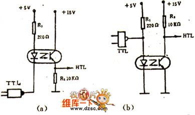
For different level conversion circuits, or input, output circuits , ifits levelneeds to be separated, it is more convenient to use optical couplers.Figures(a) and (b) circuits are 5V power supply TTL IC and 15V power supply HTL IC. Each circuit is connected and conducted level.
In figure (a), when TTL gate circuit turns on, it outputs low level, then the light-emitting diode turns on, phototransistor outputs high level; TTL gates close, then the light-emitting diode cuts off, phototransistor outputs low level. In figure (b),it uses TTL outputs high level, light-emitting diode turns on, photo transistor outputs low level; TTL conduction outputs low level, then LED isoff, and phototransistor outputs high level. (View)
View full Circuit Diagram | Comments | Reading(1877)
Car reversing anti-collision alarm circuit diagram composed of LM1812
Published:2011/9/16 1:10:00 Author:Rebekka | Keyword: car reversing anti-collision alarm


LM1812 is an excellent universal ultrasonic integrated device which can send and also receive the ultrasound. The chip includes: Pulse modulation type C oscillator, high-gain receiver, pulse modulation detector and noise suppressors detector system. It can be used for remote control, alarm, automatic door control and communications and can also be used for industrialmaterial or liquidlevel's measurement and control, range and thickness measurement, etc. It is widely applied in rain gear.
LM1812 Pin shape
LM1812 internal block diagram
LMl812 has the following characteristics: a. You can use a send / receive transducer to work. You can also use two transducers to send and receive ultrasound respectively. b. Devices is interchangeable. c. It is used without an external heat sink.
e. There is protection circuit inside the device. f. Detector output can drive 1A peak current. g. The range in the water is more than 30m. It is more than 6m in the air. h. Transmit power is up to 12w (peak). The following table shows the limit of LMl812 ultrasonic dedicated circuit operating parameters.
Extreme operating parameters
LM1812 Ultrasonic devices work dedicated schematic
。
Car reversing anti-collision alarm circuit composed of LM1812.
The control distance is adjusted by the 5kΩ potentiometer and it can be controlled within 2 - 3m.
(View)
View full Circuit Diagram | Comments | Reading(3439)
| Pages:392/2234 At 20381382383384385386387388389390391392393394395396397398399400Under 20 |
Circuit Categories
power supply circuit
Amplifier Circuit
Basic Circuit
LED and Light Circuit
Sensor Circuit
Signal Processing
Electrical Equipment Circuit
Control Circuit
Remote Control Circuit
A/D-D/A Converter Circuit
Audio Circuit
Measuring and Test Circuit
Communication Circuit
Computer-Related Circuit
555 Circuit
Automotive Circuit
Repairing Circuit