Circuit Diagram
Index 394
QM9403 three-phase motor protection circuit
Published:2011/12/7 2:04:00 Author:Ecco | Keyword: three-phase, motor protection circuit
View full Circuit Diagram | Comments | Reading(2399)
QM9403 single-phase motor protection circuit
Published:2011/12/7 1:49:00 Author:Ecco | Keyword: single-phase , motor protection
View full Circuit Diagram | Comments | Reading(2134)
QX3-13 Y-△ buck starter
Published:2011/12/7 1:54:00 Author:Ecco | Keyword: Y-△ buck Starter
View full Circuit Diagram | Comments | Reading(866)
RSCW-102 rechargeable shaver circuit
Published:2011/12/7 1:57:00 Author:Ecco | Keyword: rechargeable shaver
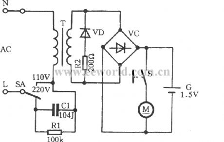
RSCW-102razor is suitable for AC , DC , and it has a charging function , and it isshown inthe circuit .
(View)
View full Circuit Diagram | Comments | Reading(2157)
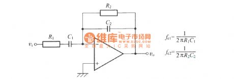
First-order bypass filter
Published:2011/12/6 1:49:00 Author:Ecco | Keyword: First-order , bypass filter

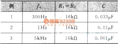
Design value Example :
(View)
View full Circuit Diagram | Comments | Reading(890)
The first-order band-pass filter composed of an operational amplifier
Published:2011/12/6 20:44:00 Author:Ecco | Keyword: first-order, band-pass filter , operational amplifier
View full Circuit Diagram | Comments | Reading(952)
8W amplifier
Published:2011/12/6 1:37:00 Author:Ecco | Keyword: 8W , amplifier

Although the TDA2030 can deliver 20 watts of output power, I deliberately reduced the output power to about 8 watts to supply 10 watt speakers. Input sensitivity is 200mV. Higher input levels naturally will give greater output, but no distortion should be heard. The gain is set by the 47k and 1.5k resistors. The TDA2030 IC is affordable and makes a good replacement amplifier for low to medium audio power systems. Incidentally, it is speaker efficiency that determines how 'loud' your music is. Speaker efficiency or sound pressure level (SPL) is usually quoted in dB/meter. A speaker with an SPL of 97dB/m will sound louder than a speaker with an SPL of 95dB/m.
(View)
View full Circuit Diagram | Comments | Reading(1001)
CA3080 variable gain amplifier circuit
Published:2011/12/6 20:26:00 Author:Ecco | Keyword: variable gain , amplifier
View full Circuit Diagram | Comments | Reading(2480)
15W amplifier
Published:2011/12/6 1:42:00 Author:Ecco | Keyword: 15W , amplifier

This amplifier uses a dual 20 Volt power supply and delivers 15 watts RMS into an 8 ohm load. Q1 operates in common emitter, the input signal being passed to the bias chain consisting of Q8, Q9, D6, D13 and D14. Q8 and Q9 provide a constant current through the bias chain to minimize distortion, the output stage formed by a discrete darlington pair (Q2,Q4) and (Q7,Q11). The last two transistors are power Transitors, specifically the 2N3055 and MJ2955. The 7.02K resistor, R16 was made using a series combination of a 4.7K, 680 Ohms, and two 820 Ohms. The 1.1K resistor, R3 was made using a 100 Ohms and a 1K resistor. You can use this circuit with any walkman or CD player since it is designed to take a standard 500mv RMS signal.
(View)
View full Circuit Diagram | Comments | Reading(991)
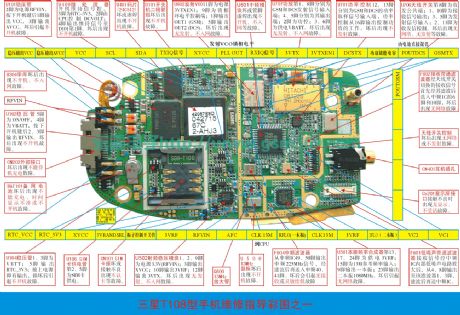
Samsung T100/T108 mobile phone repairing physical diagram (2)
Published:2011/11/29 1:40:00 Author:Ecco | Keyword: Samsung , mobile phone repairing , physical diagram
View full Circuit Diagram | Comments | Reading(7333)
Precision unity-gain buffer circuit
Published:2011/12/5 21:23:00 Author:Ecco | Keyword: Precision, unity-gain, buffer
View full Circuit Diagram | Comments | Reading(779)
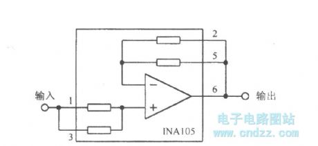
Broadband operational amplifier
Published:2011/12/5 21:25:00 Author:Ecco | Keyword: Broadband , operational amplifier
View full Circuit Diagram | Comments | Reading(803)
Wideband operational transconductance amplifier buffer circuit OPA660
Published:2011/12/5 21:24:00 Author:Ecco | Keyword: Wideband , operational, transconductance, amplifier, buffer

The internal principle circuit:
(View)
View full Circuit Diagram | Comments | Reading(1837)
Zero-drift inverting amplifier circuit
Published:2011/12/5 21:15:00 Author:Ecco | Keyword: Zero-drift , inverting amplifier
View full Circuit Diagram | Comments | Reading(678)
Zero-drift operational amplifier circuit
Published:2011/12/5 21:14:00 Author:Ecco | Keyword: Zero-drift , operational amplifier
View full Circuit Diagram | Comments | Reading(768)
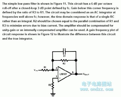
Simple low-pass filter circuit
Published:2011/12/6 1:03:00 Author:Ecco | Keyword: Simple , low-pass filter
View full Circuit Diagram | Comments | Reading(899)
DC motor current detection circuit for adjusting over threshold or not
Published:2011/12/6 1:03:00 Author:Ecco | Keyword: DC motor , current detection , over threshold
View full Circuit Diagram | Comments | Reading(1043)
High-voltage high -current operational amplifier circuit 3583
Published:2011/12/6 0:55:00 Author:Ecco | Keyword: High-voltage, high -current, operational amplifier

Figure (a) shows the methods for zerosetting ; Figure (b)shows the cylindrical package pin-out.
(View)
View full Circuit Diagram | Comments | Reading(857)
High-voltage operational amplifier circuit with internal compensation
Published:2011/12/6 0:53:00 Author:Ecco | Keyword: High-voltage , operational amplifier , internal compensation
View full Circuit Diagram | Comments | Reading(2673)
Non- inverted amplifier circuit
Published:2011/12/6 1:19:00 Author:Ecco | Keyword: Non- inverted amplifier
View full Circuit Diagram | Comments | Reading(651)
| Pages:394/2234 At 20381382383384385386387388389390391392393394395396397398399400Under 20 |
Circuit Categories
power supply circuit
Amplifier Circuit
Basic Circuit
LED and Light Circuit
Sensor Circuit
Signal Processing
Electrical Equipment Circuit
Control Circuit
Remote Control Circuit
A/D-D/A Converter Circuit
Audio Circuit
Measuring and Test Circuit
Communication Circuit
Computer-Related Circuit
555 Circuit
Automotive Circuit
Repairing Circuit


