
Circuit Diagram
Index 387
Switch voltage regulator circuit using 110V voltage doubling/220V alternating voltage input
Published:2011/11/30 21:45:00 Author:May | Keyword: Switch voltage regulator, 110V voltage doubling/220V alternating voltage input

This power supply circuit is shown in the diagram, input alternating voltage is 110V or 220V. When 110V alternating voltage power supply changesin the range of 85~132V or 220V alternating voltage power supply changesin the range of 170~265V, Sv=±1%. When load current change range is 10%~100%, Si=±5%. Output ripple voltage is ±50mV. S is 110V/220V alternating voltage option switch in the circuit, and it can bereplaced by cable jumper on printed plate. When S is closed, you can choose 110V alternating voltage input, at this time, rectifier bridge BR and resistor-capacitor components and parts R1, C1, R2, C2 make up voltage doubling rectifing circuit. When S opens, you can choose 220V alternating voltage input. In order to improve stability of voltage, you can add resistor R4 in output circuit, and the least load setted by it is 36mA.
(View)
View full Circuit Diagram | Comments | Reading(3534)
Construction indicator light circuit diagram (CD4017、CD4011)
Published:2011/11/4 2:18:00 Author:May | Keyword: Construction indicator light

Construction indicator light circuit is shown in the diagram. It needs artificially power, after circuit geting power, theindicator light flashes without breaking toremind people topay attentionon safety.
(View)
View full Circuit Diagram | Comments | Reading(2025)
Festival flashing colorful light circuit composed of RY169
Published:2011/11/9 20:50:00 Author:May | Keyword: Festival flashing, colorful light

Festival flashing colorful light circuit is shown in the diagram. ACvoltage isfull-wave bridge rectified by diodes VD1~VD4, voltage regulated by resistors R1, R2 and voltage regulator diode VD5,filtered by capacitor C1 to generate 6V smooth DC voltage, and it is used for the whole circuit. Diode VD6 is used forisolation. IC1 is colorful light control application specific intergrated circuit RY169, andits internal structurehas brightness grade and output speed oscillators, and the oscillator frequency depends on RP1, C2 and RP2, R3, C3. After it gets power, IC1's pin 9~12 output changing pulseto passresistors R5~R8andadd to thyristors VT1~VT4's controlling electrodes, then its conduction angle changes, thereby it generates thestars flashing effect. IC3's pin 2 is the control end oflight chain lighting direction. (View)
View full Circuit Diagram | Comments | Reading(1142)
Six-way loop lantern control circuit composed of HFC3040
Published:2011/11/9 20:38:00 Author:May | Keyword: Six-way loop , lantern control

Six-way loop lantern control circuit composed of HFC3040 module can drive six-way lantern loop to flash, andit hastwo different loop speeds, and it is shown in the diagram. Because the circuit skillfully uses flashing integrated module HFC3040 to make circuit structure simple and cost low. IC1 is theflashing special integrate circuit HFC3040, and its working voltage range is 1.5~5V. So 220V ACvoltage is buck limited by R1, half-wave rectified byV1 to makeLED emit light. At the same time, the two ends ofLED 's about 1.6V steady DC voltageis filtered by C1 toofferpowerfor integrate circuit. Because TR's trigger ends connectto ground,it immediately is triggered to work after getting power. Six output ends L1~L6 is in low level orderly, so six PNP triodes VT1~VT6 are breakover orderly, unidirectional thyristors VS1~VS6and lanterns H1~H6 arelit one by one. (View)
View full Circuit Diagram | Comments | Reading(950)
Low input current low power consumption peripheral driver circuit
Published:2011/11/9 20:21:00 Author:May | Keyword: Low input current , low power consumption, peripheral driver circuit
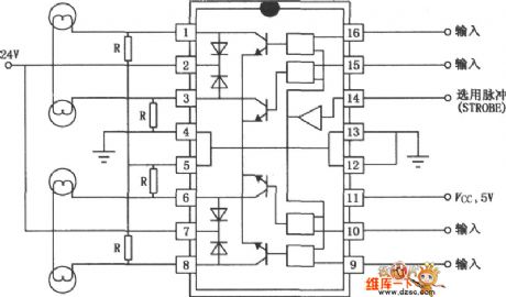
SN75436/75437A/75438 is low input current, low power consumption monolithic four-channel, OC, inverted output peripheral driver, which is used ashigh current, high voltage load driver. This chip's input current is low, power consumption islow, output voltage is high, output impedance ishigh,and it has theoutput clamping diode. The diagram is wiring diagramwhen it is usedas lamp driver.
(View)
View full Circuit Diagram | Comments | Reading(960)
AC voltage controller circuit using unidirectional thyristor
Published:2011/11/30 20:10:00 Author:May | Keyword: AC voltage controller, unidirectional thyristor
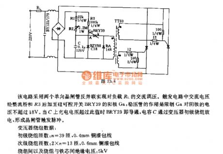
This circuit uses two unidirectional thyristors connectedinversed and in parallel to realize AC voltage adjusting forload RL. Trigger circuit's AC voltage is added to anode Ga of silicon controlled switch BRY39through rectifier bridge and R3,and the voltage regulator tube is used tolimit Ga's voltage oncathode being not more than 18V. When charge voltage on C ismore than this value, BRY39 will be breakover, capaciotr C discharges through transformer's first winding toform thyristor trigger pulse.Transformer winding data:first winding turns: n=39 , 0.4mm copper enameled wiresecondary winding turns: 2×n=13 , 0.6mm copper enameled wireisolation voltage between windings and iron core: 5kV (View)
View full Circuit Diagram | Comments | Reading(2236)
Tv power photo observation circuit using LED
Published:2011/11/30 20:12:00 Author:May | Keyword: Tv power photo observation, LED

When switch places (2) , output voltage is the samewith theinput voltage. If voltage is normal (200~240V), two luminotrons are not bright. When voltage rises to 250V, point A 's potential rises to make red luminotrons birght, switch places (1) tomake output be 220V, red luminotrons go out again. When voltage drops to 190V, green luminotronsarebright, switch places (3).
(View)
View full Circuit Diagram | Comments | Reading(717)
Charging circuit using UBA2008 charging switch chip
Published:2011/11/30 20:28:00 Author:May | Keyword: Charging circuit , charging switch chip

UBA2008 is the charging intelligent management chip with pulse way produced by Philips. The device integrates a low- resistance power switch which can be used for charge controlling of single cell Li-Ion or three NiMH cells or in the pre- charging or fast charging modes. It has current limiting , overvoltage protection, thermal protection and electrostatic discharge (ESD) protection, and it integrates the security mechanisms in battery charging process to ensure its safe operation.
(View)
View full Circuit Diagram | Comments | Reading(998)
Voice controlling lamp (FC52) circuit
Published:2011/11/3 0:55:00 Author:May | Keyword: Voice controlling lamp

The diagram is voice controlling lamp circuit. This circuit consists of operational amplifier FC52, bi-stable flip-flop, relay J, piezoelectric crystal speaker y. The bi-stable flip-flop consists of double NAND gate TMY23A, when speaker y works, it can change voice signal to electric signal.
When clapping generates voice, Y will change voice signla to electric signal,then it will be added to opposite phase input end of FC52 to be enlarged. After enlarging, the output pulse isadded to bi-stable flip-flop. (View)
View full Circuit Diagram | Comments | Reading(1136)
Constant pressure source adopts operational amplifier TAA861
Published:2011/11/10 0:16:00 Author:May | Keyword: Constant pressure source, operational amplifier

Diagram (a) circuit's output voltage is adjusted by regulation resistor Rp, and ithas regulating characteristics . Diagram (b) is the relationship curve of output voltage bias ΔUAandload current IA (0~70mA), diagram (c) is the relationship curve of input voltage UE.
Main technical data
input voltage: UE=11~20V
output voltage:UA=8~18V
maximum output current: IA=70mA
voltage regulation factor (ΔUE=1V, UE=15V, UA=10V, IA=40mA); F=ΔUA/UA=1×10-4
load regulation factor (IA=0~60mA, UE=15V, UA=10V); F=ΔUA/UA=4×10-4
dynamic resistance: Ri=60mΩ
output voltage temperature coefficient: 3~5×10⁻⁵V/K (View)
View full Circuit Diagram | Comments | Reading(1078)
Car headlight automatic controller circuit composed of 555
Published:2011/11/3 1:21:00 Author:May | Keyword: Car headlight, automatic controller, 555

The diagram is car headlight automatic controller circuit. This controller consists of single-shot delay circuit ( IC1, Rl, R2、RD, C1), multivibrator ( IC2, R3, R4, C2) , intergrated circuit( 7812) , V-MOS power driving tubes BG2, BG3 to separately drive car's two headlight. The power source of this controller uses car's +24V storage battery, and it provides DC +12V voltage for IC1, IC2 afterregulation by IC3.
When the front has no opposite cars, photoresistor RD presents high level becasue it does not receive shine, then the corresponding IC1 resets because pin 2 is in high level, then pin 3 outputs low level.It makes IC2 reset because pin 4 is low level, pin 2 outputs low level, then BG1 stops, BG2, BG3 isbreakover, two headlights arelighten.
(View)
View full Circuit Diagram | Comments | Reading(2450)
LED display electronic voltmeter circuit
Published:2011/11/3 1:04:00 Author:May | Keyword: LED display, electronic voltmeter

This circuit mainly consists of six light-emitting diodes, two integrated circuits and some resistors. It can display the voltage ofcar, motorcycle or electric bicycle batteriesaccording tothe quantityof light-emitting diode lights. Its usage is very convenient.
(View)
View full Circuit Diagram | Comments | Reading(2065)
The traffic light automatic controller circuit in traffic intersection
Published:2011/11/3 1:55:00 Author:May | Keyword: traffic light , automatic controller , traffic intersection

The input 8V voltage isregulated by78M05 to offer VDD=+5V power supply voltagefor 555.
Whenthe circuitgets power, the trigger pulse delaysby passingIC1 (CD4011) gate circuit and R1, C1,then it isadded to IC2's pin 2 after being differential by C2, R22, then the trigger IC2 outputs high level to be in transient state, and its transistion state timing time depends on K1's position, when delay td=1.1RC6, itsets time in 60s, 45s, 30s. When transient state finishes, IC2's pin 2 is inlow level, it isdifferential through C3, R23 to trigger IC3 and form second level signal-shot delay.
This circuit is monitor display part of control circuit. If it is really used to traffic command, it should use control signal to driver solid state relay, then the light bulb works. (View)
View full Circuit Diagram | Comments | Reading(2071)
Fancy lantern circuit
Published:2011/11/10 1:15:00 Author:May | Keyword: Fancy lantern

This circuit is 3-road fancy lantern circuit whichuses fractional frequency to divide trigger bidirectional thyristor audio frequency signal into high, middle, low, and they are usedseparately to trigger SCR1, SCR2, SCR3 controlled silicon to control blue, green, red fancy lanterns. With the change of music rhythm, three kinds ofcolor changes, and it is very impressive.
(View)
View full Circuit Diagram | Comments | Reading(983)
DC motor commutator circuit
Published:2011/11/3 1:58:00 Author:May | Keyword: DC motor commutator
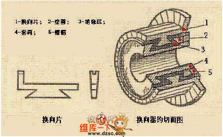
The important component of DC motor, and its functionis to transform the DC current to AC current in the coil ofelectric brush or transform the AC electromotive force to DC electromotive force.
diagram: DC moitor commutator circuit (View)
View full Circuit Diagram | Comments | Reading(2290)
The commutating pole circuit of DC motor
Published:2011/11/23 21:19:00 Author:May | Keyword: commutating pole , DC motor
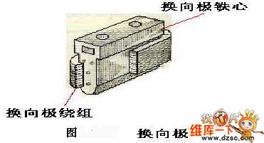
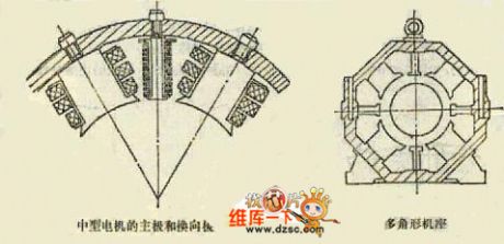
The schematic diagram of the main pole and the interpole (View)
View full Circuit Diagram | Comments | Reading(1184)
Miner lamp battery alarm circuit diagram
Published:2011/11/9 21:49:00 Author:May | Keyword: Miner lamp battery alarm

This circuit uses the miners lamp battery as its power source, and it isinstalled in ore cap, when gas is over, the head lamp buld will automatically flash, and itis accompanied by alarm sound.
This circuit uses less component, and ithas no influenceon miner's normal work,it costs low with adjustable emergency alarm, and it is easy to carry.
(View)
View full Circuit Diagram | Comments | Reading(884)
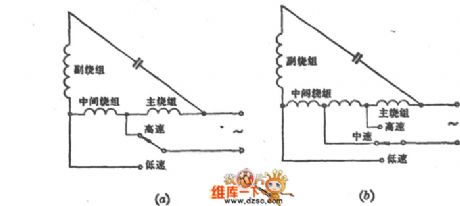
L1 winding tap speed regulation circuit
Published:2011/10/27 22:43:00 Author:May | Keyword: L1 winding tap , speed regulation
View full Circuit Diagram | Comments | Reading(538)
π type filter circuit composed of ISO122/124
Published:2011/11/9 21:53:00 Author:May | Keyword: filter

The diagram is π type filter circuit composed of ISO122/124. ISO122/124 internal osicillator set the modem frequency at 500KHz. In order to suppressthe noise from DC/DC convertor, ituses π type filter composed of inductors and capacitors wave filtering at every power source end. After wave filtering, ISO122/124 output end's 500KHz ripples are suppressed to 20mV, then it uses low-cost OPA602 ( or OPA237) to make up two pole low-pass filter forfurther wave filtering, and the two pole low-pass filter cutoff point is 100KHz.
(View)
View full Circuit Diagram | Comments | Reading(1255)
Digital counting demonstration circuit
Published:2011/10/27 22:47:00 Author:May | Keyword: Digital counting demonstration
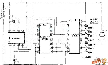
555 timer is used as clock to drive RS7490 decimal system counter, then theBCD output of counter isreturned to 7-segment tube. Ajusting R7 can change the frequency of clock. (View)
View full Circuit Diagram | Comments | Reading(1422)
| Pages:387/2234 At 20381382383384385386387388389390391392393394395396397398399400Under 20 |
Circuit Categories
power supply circuit
Amplifier Circuit
Basic Circuit
LED and Light Circuit
Sensor Circuit
Signal Processing
Electrical Equipment Circuit
Control Circuit
Remote Control Circuit
A/D-D/A Converter Circuit
Audio Circuit
Measuring and Test Circuit
Communication Circuit
Computer-Related Circuit
555 Circuit
Automotive Circuit
Repairing Circuit