
Circuit Diagram
Index 384
50MHz opto-electrical detecting circuit
Published:2011/12/1 0:46:00 Author:May | Keyword: opto-electrical, detecting

Parallel-tuned circuit is suitable for single GE photod circuit shown in the diagram. When the number of paralled photods isup to five, it requires to use series tuning. Tuning capacitor uses 10pF, and frequency response can reach about 400MHz. T1's primaryis 2 laps,and the secondaryis 7 laps, they are wound on high frequency plastic core.
(View)
View full Circuit Diagram | Comments | Reading(874)
48V/2A voltage regulator circuit
Published:2011/11/24 0:59:00 Author:May | Keyword: voltage regulator
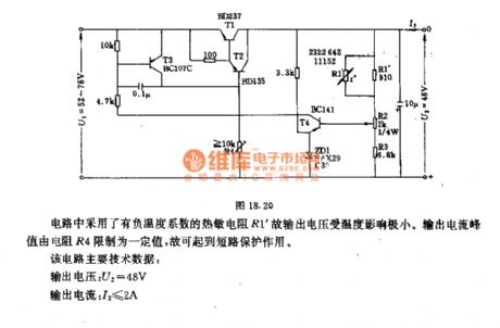
The circuit uses thermistance R1' with negative temperature coefficient, so the temperature has little influence on output voltage. Outrput current peak value is confined to a definite value by resistor R4, so it has the usage of short-circuit protection.
This circuit main technical data:output voltage: U2=48Voutput current: I2≤2Ainput voltage: U1≤40mΩT1 radiator thermal resistance: RthK≤0.63grd/WT2 radiator thermal resistance: RthK≤30grd/Woutput voltage variable quantity:when environmental temperature θU=0~60°C △U2=100mVwhen output current I2=0~2A (U1=constant) : △U2=80mAwhen input voltage U1=52~78V (I2=0) △U2=30mA (View)
View full Circuit Diagram | Comments | Reading(3218)
4A/12.3V lithium ion battery charger circuit with LTC4008 control chip
Published:2011/11/24 1:01:00 Author:May | Keyword: 4A/12.3V , lithium ion , battery charger, control chip

4A/12.3V lithium ion battery charger circuit uses LTC4008 as control chip.
(View)
View full Circuit Diagram | Comments | Reading(1592)
50kHz frequency light emission cuircuit
Published:2011/11/24 1:19:00 Author:May | Keyword: frequency light emission

This circuit uses center frequency 50kHz impulse speed modulation system. Audio frequency feedback transmitter can change impluse speed, and it isused to drivethe LEDcoupled to optical fiber. LED uses General Electric LED 5C or similar LED. Optical transistor islocated on another end of optical fiber toreceive and demodulate light signal and make audio frequency recover.
(View)
View full Circuit Diagram | Comments | Reading(869)
Light comparator circuit
Published:2011/11/24 1:11:00 Author:May | Keyword: Light comparator
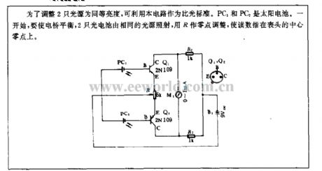
In order to adjust two light source to the same brightness, itcan use this circuit as light compare standard. PC1 and PC2are solar batteries. At the start, it should make the bridge keep balance, and the two photocellshas the same light source, and it uses R as zero adjustment to make the read number point at center zero of guage head.
(View)
View full Circuit Diagram | Comments | Reading(865)
Slotted tip control photoelectric control circuit
Published:2011/12/1 1:09:00 Author:May | Keyword: Slotted tip control, photoelectric control

Usually, 2CU2B photosensitive diode shuts out light source by slitting carborundum discs tomake relay failure to actuate. But, when slitting carborundum discs is open byseveralor tens of nib ( the number depends on the quality of carborundum discs) , carborundum discs arefret, when itaborts nib, it can not shut out light source ( about 1mm), because 2CU2B has light, it can generate 5~10µA light curret to makeB1, BG2 compositive clad pipe breakover, Schmidt trigger output negative impulse, monostable circuit output positive impulse and BG7 breakover, execution relay action. Then it can drive middle relay and miniature solenoid close once, and theclosed time depends on monostable delay circuit. After slitting carborundum discs shut out light source again, nib slitting continue start, and the action repeats.
(View)
View full Circuit Diagram | Comments | Reading(1235)
Multidigit scaling circuit for performance
Published:2011/12/1 1:29:00 Author:May | Keyword: Performance, multidigit scaling
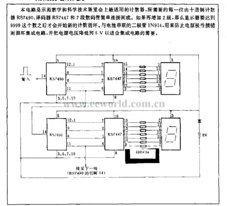
This circuit is the countersuitablefor demonstration teaching and technology exhibition, and it is composed of the counting counter RS7490, encoder RS7447 and seven segment digital tube. If it is added two stage again, display can start new count cycle only when it gets the number of 9999. Diode IN194 connected to battery in series with battery is used to prevent damage integrated circuit from misconnection power polar and reduce power supply boltage to 5V in order to fit the need of intergrated circuit.
(View)
View full Circuit Diagram | Comments | Reading(850)
Photoelectric coupler control thyristor circuit
Published:2011/8/28 21:24:00 Author:Jessie | Keyword: Photoelectric couplers, thyristor

In the circuit, if photoelectric coupler' light emitting diodeflows6 ~ 10mA current, the phototriode is connected, then the thyristor is connected, load RL has current; Conversely, nocurrent flows through load. Diode is used toprovideDC power to light activated triode, resistor RVis connected tocapacitor C inseries in order to storage control energyat power negative half cycle. Regulator tube make light activated triode have stable 15V voltage. This circuit's maximum switch currentis 4A, thyristor phase shift angle range is 0~180°.
(View)
View full Circuit Diagram | Comments | Reading(913)
Low power supply voltage thyristor control circuit
Published:2011/8/28 21:34:00 Author:Jessie | Keyword: Low power supply voltage, thyristor

This circuit's power supply voltage is 12~16V, it can be used in low pressure vessels such as toy train. It makes S566B as trigger circuit to generate control thyristor's connection. DC power is supplied by rectifier voltage circuit, R1 is the step-down resistor. The role of transistor T1 is to reduce control dead zone. Because this circuit's load current is so low, it can be connected a 1~2W bulb to make the Bi-directional thyristor current higher than the maintaining current. Because the transformer power output is small, when the Bi-directional thyristor is connected, transformer's leakage is equal to big series resistor, which can cause short-term voltage stopped, and it should be connected the capacitor C4 in series. (View)
View full Circuit Diagram | Comments | Reading(1642)
Lighting dimmer using thyristor AC power
Published:2011/8/28 21:58:00 Author:Jessie | Keyword: Lighting dimmer, thyristor, AC power

This circuit can continuously adjust lamp's brightness which below 3kW. The choosen Bi-directional thyristor can bear 1200V, so the circuit power can be supplied by 220V or 380V grid, the latter output power can reach 4.4 kW. Trigger circuit dc power is supplied by rectifier bridge BY179. When switch S is closed, trigger capacitor C5 is charging. When the recharging voltage is over BRY39's gate voltage, the pipe is connected, C5 is discharged, so transformer output pulse supplys for the thyristor. Changing the potentiometer R2 can adjust the brightness of the light. (View)
View full Circuit Diagram | Comments | Reading(2527)
Storage battery automatic charger 3
Published:2011/11/10 2:44:00 Author:May | Keyword: Storage battery, automatic charger

Familiar storage battery automatic charger can achieve the purpose of automatic control by detecting storage battery voltage when it ischarging. But when it has charging current, justified voltage of storage battery will be too high, so it is hard to decide the degree of charging by storage battery voltage. This text introduces an automatic storage battery charger.
The circuit is shown in diagram 4-10. It is theautomatic charger and its core is thethyristor components. When charger is connectedto discharged storage battery, thyristor VS is breaking over at every positive half period, and it will charge to the battery. In the end of positive half period, when charge voltage is lower than storage battery voltage, thyristor VS is cut off. When positive half period sarts, VS is in the cut-off stateat this time, the comparing of charge voltage and reference starts in order to decide whether VS is breaking over or not. When justified voltage of battery reaches to the certain value (about 13.5V), VT will not have current and VS will be cut off. (View)
View full Circuit Diagram | Comments | Reading(1396)
Thyristor control flash circuit
Published:2011/8/28 21:37:00 Author:Jessie | Keyword: Thyristor, flash

The figure shows two flash circuits controlled by thyristor. The former uses neon tube FV1 to connect the voltage trigger thyristor, the latter uses UJT1 to connect the trigger thyristor. The formeris AC power supply,the latter isDC power supply. In order to make lamp flash, it is added commutation capacitor to circuit.
(View)
View full Circuit Diagram | Comments | Reading(1696)
Thyristor controlling DC motor positive and negative rotating circuit
Published:2011/8/28 21:26:00 Author:Jessie | Keyword: Thyristor, DC motor, positive rotating, negative rotating

View full Circuit Diagram | Comments | Reading(1124)
Ordinary thyristor dimming circuit
Published:2011/8/28 21:21:00 Author:Jessie | Keyword: thyristor, dimming

View full Circuit Diagram | Comments | Reading(1327)
1X0773CE ( video ) infrared remote control transmitter circuit
Published:2011/8/31 1:41:00 Author:Jessie | Keyword: infrared, remote control transmitter
IX0773CE is infrared remote control transmitter circuit, whichissuitable for video, etc. The Internal circuit is composedof theoscillator, scanning, signal generator, data controller, modulation circuit, memory circuits, keyboard input circuit and coding circuit, etc. Technical features: it usesCMOS integrated circuit withlow power consumption; it has four inputs and eight outputs, which can form 4X8 keyboard matrix with 32 kinds of control functions; Oscillating circuit and 455kHz crystal cangenerate 38kHz timing signal; it can prevent multiple keys frompressing at same timeand causing misoperation; it uses 20-pin DIP.
(View)
View full Circuit Diagram | Comments | Reading(2634)
BIJ9148 ( general ) infrared remote control transmitter circuit
Published:2011/8/31 1:39:00 Author:Jessie | Keyword: general, infrared remote control, transmitter
BL9148 is general infrared remote control transmitter circuit. The Internal circuit is composedof theinput circuit, oscillating circuit, points frequency circuit, single clap/continuous command control circuit, the clock signal generator, instructions data control circuit and modulation circuit, etc. Technical features: it uses CMOS technology, power consumption is extremely low; Supply voltage range is 2.2 ~ 5.5 V; Peripheral components is less; It has external LC or ceramic filter; it uses 16-pin DIP.
(View)
View full Circuit Diagram | Comments | Reading(2784)
BUl301F ( TV and video) infrared remote control transmitter circuit
Published:2011/8/31 1:38:00 Author:Jessie | Keyword: infrared, remote control transmitter
BUl301F is theinfrared remote control transmit circuit. The Internal circuit is composedof theoscillator frequency device, drive, points, output drives, timing signal generates control circuit, shift register, read-only memory, keyboard scan signal input circuit and keypad scanning signal output circuit, etc. Technical features: CMOS technology, low power consumption; higher integration,less peripheral components;lowpower supply voltage;20-pin DIP.
(View)
View full Circuit Diagram | Comments | Reading(2617)
BA5101( Household appliances) infrared remote control coding circuit
Published:2011/8/31 1:32:00 Author:Jessie | Keyword: infrared, remote control coding
BA5101 is infrared remote controlcoding circuit, which is applicable to the household appliances such as electric fans. It supports the use of the BA5201.
(View)
View full Circuit Diagram | Comments | Reading(2931)
DIJ50462 (TV) infrared remote control transmit circuit
Published:2011/8/31 1:30:00 Author:Jessie | Keyword: infrared, remote control transmit
Technical characteristicsCMOS technology, low power consumption.Wide range power supply voltagein 2.2~5.5V.Only when people enter the button, oscillating circuit will produce oscillation, so power consumption is low.24-pin DIP.
OSCIN and OSCOUT sides externally connect LC or ceramic filters to generate 480KHZ and 455KHZ reference frequency, then it generates 40KHZ or 38KHz frequency carrier by internal fractional frequency. Emission control signal uses pulse position modulation (PPM), where 0 code is the negative pulse with the duty cycle in 1 / 4, 1 code is the negative pulse with duty cycle in 1 / 8. Negative pulse modulation is on the 38KHZ 40KHZ carrier.
(View)
View full Circuit Diagram | Comments | Reading(2607)
CX23040 ( TV and video)infrared remote control transmitter circuit
Published:2011/8/31 1:22:00 Author:Jessie | Keyword: infrared, remote control transmitter
CX23040 is infrared remote control transmit circuit, which is applicable to the TV and video, etc. It has eight inputs (pin 1 ~ 5, pin 25 ~ 27) and eight outputs (pin 9 ~ 13, pin 15 ~ 17), can form the 8x8 keyboard matrix.
(View)
View full Circuit Diagram | Comments | Reading(2836)
| Pages:384/2234 At 20381382383384385386387388389390391392393394395396397398399400Under 20 |
Circuit Categories
power supply circuit
Amplifier Circuit
Basic Circuit
LED and Light Circuit
Sensor Circuit
Signal Processing
Electrical Equipment Circuit
Control Circuit
Remote Control Circuit
A/D-D/A Converter Circuit
Audio Circuit
Measuring and Test Circuit
Communication Circuit
Computer-Related Circuit
555 Circuit
Automotive Circuit
Repairing Circuit