
Circuit Diagram
Index 388
Morning and evening light-operated switch circuit
Published:2011/11/23 21:07:00 Author:May | Keyword: light-operated switch, Morning and evening
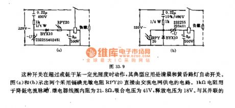
This kind of switch acts when it is above or below a cetrtain illumination, andits typical application is morming and evening street light auto switch. Diagram (a) and (b) show two circuits which adopt cadmium iodide photoresistor RPY20 directly supplied by AC electric fence. 1KΩ resistor isused to reducecurrent pulse. Relay coil 's essential resistance is 21.8Ω, and the pull-in voltage is 45V, release voltage is 18V. The capacitor connected with it in parallel makes up the RC with time constant in 0.1s, in order to minish the pulse DC voltage output by short-lived light flash and smoothness diode and prevent relay tremble, the relay touch point in diagram (a) circuit is normal closed. During the day,theillumination intensity is strong ( >31~45lx), thephotoresistance resistance is small, relay acts, andtouch point isopen, lamp goes out. At night, when illumination intensity is weak (<8.5~11lx) , on the contrary, the relay touch point in diagram (b) is normally open, its work is opposite from diagram (a). (View)
View full Circuit Diagram | Comments | Reading(1118)
Long-time turnoff delay circuit
Published:2011/11/10 1:24:00 Author:May | Keyword: Long-time, turnoff delay
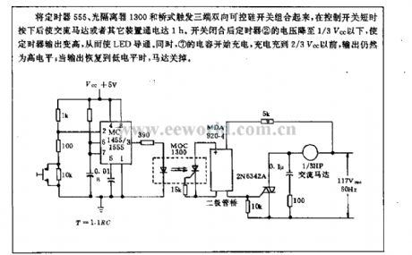
The timer 555, optoisolator 1300 and bridge trigger three-terminal bidirectional thyristor switch is combined in the circuit, after control switch ispressed with short time,it will makeAC motor or other devicebreakover with 1h. After switch isclosed, timer 2 's voltage drops to under 1/3Vcc tomake timer output rise, thereby LED isbreakover. At the same time, 7 capacitor starts charging, befor it is charged to 2/3Vcc, the output is still in high level; when output recovers to low level, the motor turns off.
(View)
View full Circuit Diagram | Comments | Reading(1047)
Human infrared remote sensing lamp circuit
Published:2011/11/3 22:14:00 Author:May | Keyword: Human infrared remote sensing lamp

The diagram is human infrared remote sensing lamp circuit. It uses trace infrared heat sent out by human to remote control the open or close of lap. This human infrared remote sensing lamp trigger sensitivity is very high ( can work in 10m distance), anti-jamming ability is strong, and ittruly achieces full automation.
(View)
View full Circuit Diagram | Comments | Reading(3651)
Floodlight energy-saving controller circuit composed of CD4069
Published:2011/11/4 1:28:00 Author:May | Keyword: Floodlight energy-saving controller
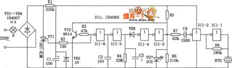
Floodlight energy-saving controller can make floodlight closed during the day, when someone moving generates sound at night, floodlight it automatically works,ao it has the energy-saving and practical features, and it is suitable for stair aisle illuminator's control.
(View)
View full Circuit Diagram | Comments | Reading(932)
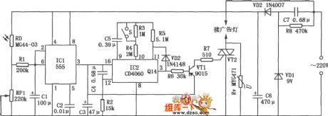
Advertisement lamp automatic control circuit (555、CD4060)
Published:2011/11/4 1:27:00 Author:May | Keyword: Advertisement lamp automatic control
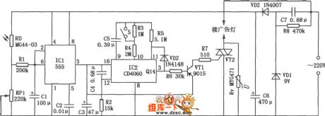
Most advertising lights have good publicity function only before 12 o 'clock at night, after midnight, pedestrian isscarce,then itloses theadvertising significance. This advertisement lamp automatic control circuit can connect power of advertising light brand automaticlly in the evening, at the same it starts timing, after 4 ~ 6 hours at midnight, it automatic cuts off power, so it realizes the automatic control and energy-saving purpose. The diagram is advertising light automatic control circuit, andit consists of power transformation, optical and timed components.
(View)
View full Circuit Diagram | Comments | Reading(1665)
Wireless mouse circuit
Published:2011/11/4 1:17:00 Author:May | Keyword: Wireless mouse
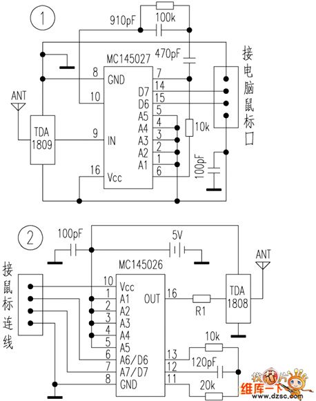
This device adopts encoding and decoding circuit MC145026/ MC145027 and RF transmitter / receiver module TDA1808/ TDA1809, and it can beflexibly operated inthe range of 10~120m, and people have no need to change orginal mouse eterior apperance and inside circuit in the making peocess,and itis convenient and reliable, very suitablel for homemade lovers. Generally speaking, there are four circuit lines inside mouse and computer connect line ( this circuit device can receive four data wire inputs, and reader can choose according to practical situation of theirself mouse ), they are seperately power source anode, power souce ground, data wire 1, data wire 2. The circuit has no need to change mouse and computer, no need to intall additional mouse to drive software, and all the functions of orginal mouse can benormal used.
(View)
View full Circuit Diagram | Comments | Reading(18882)
Advertisement lamp automatic control circuit composed of 555、CD4060
Published:2011/4/23 9:07:00 Author:May | Keyword: Advertisement lamp automatic control
Most city advertising light have good publicity function only before night 12 o 'clock, after midnight, pedestrian scarce, also lost advertising significance. This advertisement lamp automatic control circuit can connect power of advertising light brand automaticlly in the evening when the day was black, at the same time it starts timing, after 4 ~ 6 hours at midnight automatic cut-off power, so as to realize the automatic control and energy-saving purpose. As shown in the diagram is advertising light automatic control circuit, it consists of power transformation, optical and timed components.
(View)
View full Circuit Diagram | Comments | Reading(1432)
Touching dimmer circuit composed of S7232
Published:2011/11/3 21:37:00 Author:May | Keyword: Touching dimmer
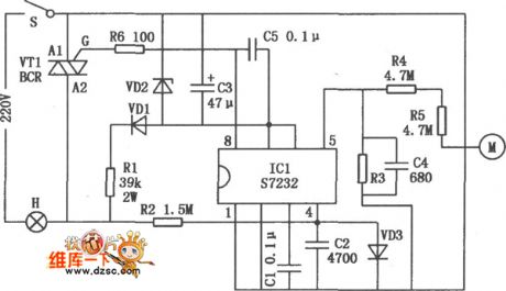
Touching dimmer circuit is shown in the following diagram. It uses finger touch control pieceto realize turning on, off or stepless adjustment for incandescent light. It is used in the dimmer of filament lamp, small AC motor's stepless speed regulation.
(View)
View full Circuit Diagram | Comments | Reading(2521)
Car light flashing circuit composed of 555, CD4017B
Published:2011/11/3 21:31:00 Author:May | Keyword: Car light flashing, 555
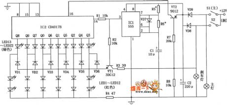
Car light flashing circuit mainly consists of red, green lights. When it emits light,red light islighten from middle to end, and green light jumps from end to middle. When car drives normally, red light and green light arelighten according to program order. When it is braking, all green lights die out, but all red light are lighten. Car light flashing circuit is shown in the diagram.
(View)
View full Circuit Diagram | Comments | Reading(2676)
Circular lights control circuit (555, C180)
Published:2011/11/4 1:03:00 Author:May | Keyword: Circular lights control, 555
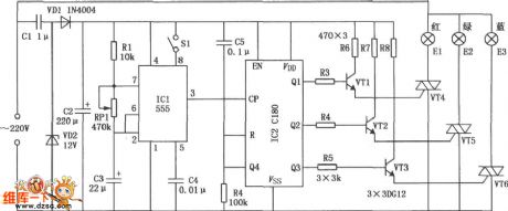
Circular lights control circuit is shown in the diagram. The circuit contains three Gezer lights E1, E2 and E3, it generates red light, green light and blue light. According to the principle of mixed color, red, green and blue can be mixed in different combinations, which includes seven color lamplight of red, green, blue, yellow, purple, green and white. Seven color light flashes in cycle , and the circulation speed is adjustable, and thecircuit has fixed color switch, which can fixed display needed colors.
(View)
View full Circuit Diagram | Comments | Reading(1059)
Gate controlling delay light circuit diagram
Published:2011/11/9 20:14:00 Author:May | Keyword: Gate controlling , delay light

Gate controlling delay light uses gate switch to control the turning on or off of the lamp, during the day, the light can not be open because of light control. At night, if you open the door, at the same time, the lamp is turned onautomatically and delayed period of time,and the circuit is shown in the diagram. The circuit consists of a four-dual input end orNOT gate CD4001, among them, gate D1 makes up thelight control and trigger circuit, gates D2, D3and R3, R1 make up single shot trigger toplay a roleof delay close. Transistor VT and relay K are used as lamp EL's switch control circuit. Optical transistor VTP plays a role in light control.
(View)
View full Circuit Diagram | Comments | Reading(1006)
Electronic touch dimmer circuit composed of CD4028
Published:2011/11/9 21:47:00 Author:May | Keyword: Electronic touch dimmer
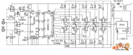
The diagram is touch dimmer which uses a kind of parameters of solid state relays (PSSR) as main control component, and it is not normally used bidirectional thyristor. The light adjusting process uses touching method,and itis convenient, and the circuit is shown in the diagram. This circuit consists of touch control signal input circuit, stepper control pulse generator, pulse / down counter, pulse signal decoding distributor, ten control parameters of solid-state switches and relays, etc.
(View)
View full Circuit Diagram | Comments | Reading(2804)
New degaussing principle circuit
Published:2011/11/11 2:03:00 Author:May | Keyword: degaussing principle
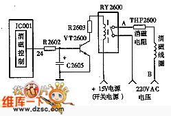
Because the voltage on capacitor C2605 can not mutation, this high level signal thorugh R2602 resistor first charges to C2605, because charging time constant is very big, the high level potential build at C2605 lags to the start time. Whenit isin starting process, capacitor finishes charging, VT2600 tube's base is inhigh level and breakover, relay RY2600 coil generates current access, its touching point is cut-off, degaussing circuit power source ( AC) accessis cut, thereby itfinishes the cut-off movement of degaussing circuit.
diagram 3: TV new type degaussing circuit
After shutdown, IC001's pin changes to low level, capacitor C2605discharges through VT2600's b-e junctions and IC001 internal concerning circuit, and the discharging time constant is also very high, so VT2600 tube changes to cutoff state after delay period of time, relay RY2600 again recovers to normal close state for degaussing next time.
(View)
View full Circuit Diagram | Comments | Reading(1401)
Blind electronic compass circuit
Published:2011/11/30 21:05:00 Author:May | Keyword: electronic compass

The core device IC1 of electronic compass is a piece of hall-effect integration sensor UGN-3501M, its internal structure includes a hall unit and a linear differential amplifier with differential emitter-follower output.
The circuit principle is shown in the diagram: the integrated hall sensor IC1 changes the earth's magnetic field to differential output voltage; this voltagepasses IC1's two output ends pin 8 adn pin 1 and resistors R1 and R2,then it is added toanother difference amplifier IC2 ( μA741) . When IC1 output is zero,RP is used to adjust the output voltage of IC2; capacitor C1 isused to suppress parasitic oscillation. R8, C2 , and VD (1N4148)are thecharge and discharge devices of time-base circuit. (View)
View full Circuit Diagram | Comments | Reading(2534)
Thirty bits falling water lamp digital control circuit
Published:2011/11/30 20:39:00 Author:May | Keyword: Thirty bits, falling water lamp, digital control
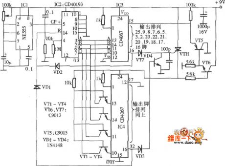
The color lamps controllingcircuit shown in the chart hasthirty outputs, whichcan control thirty lamps todo falling water sports by the external driver circuit, and it can beused as large size decoration variegated lamp controller, and the circuit is shown in the diagram. The diagram consists of control impulse generator, control impulse distributor and variegated lamp control output circuit.
(View)
View full Circuit Diagram | Comments | Reading(1078)
Blind crowing device circuit
Published:2011/11/23 21:45:00 Author:May | Keyword: Blind crowing device
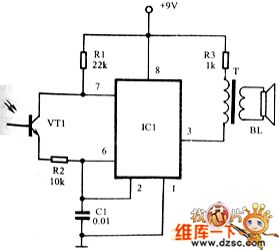
The blind always feel not convenientwhen they usetiming clock to crow herald the break of a day,so using blind crowing device circuit to make crowing device is very convenient.
Transistor VT1 is optical transistor, when it has different illumination, its resistance value changes comparatively large, integrated circuit IC1 (5G1555) makes up free-running multivibrator, its oscillator frequency rises along with the add of lumen output. The oscillator frequency and dutyfactor of oscillator depends on resistor R2, photoelectric cell VT1 (3DU22) and capacitor C1. Resistor R2 ensures the upper limit frequency at about 6.5KHz. Photoduodiode VT1's dark resistor makes lower limit frequency fix at about 1Hz.
Sound relationship with the Sky output as follows:
Sky output/ VT1 resistor/ frequency
sunshine enough/100Ω/6500Hz
evening/ 10K/3000Hz
starlight/ 10M/ 2~4Hz
(View)
View full Circuit Diagram | Comments | Reading(898)
Analog qigong infrared light generator circuit
Published:2011/11/9 21:25:00 Author:May | Keyword: Analog qigong , infrared light generator

The following diagram is the principle diagram of Analog qigong infrared light generator circuit, andtransistor VT1 ect makes up unijunction pulse oscillator to generate about 10Hz STW, and it is filteredthrough R3, C2 and amplified byVT2 to drive infrared LED VD2 andgenerate pulse infrared light. PR is used for frequency vernier regulation, VD1 is the power source indication, VD2 is HG41domestic infrared LED, andits peak wavelength isgreater than 0.9μm, response time is smaller than 10ms.
Because qigong differs from man to man, and this generator only simulates outside gas information in some ways ( outside gas information is extremely rich) ,it allows component value to have wide change. HG41 isadded lens to makedivergence angle smaller than 20 degree, and its directivity is good. When people use it, peopel canput the infrared tube to aim at spontaneous in the palm or bellybelownavel hole, then it can generate sense of hotness after about 10 min. This generator can beused to qigong medical treatment or body stengthen experiment.
(View)
View full Circuit Diagram | Comments | Reading(999)
Relay detection circuit diagram
Published:2011/11/3 22:51:00 Author:May | Keyword: Relay detection

Diagram a is resistor to measure coil.Multimeter chooses R×100 Ω file. Diagram b is relay to measure the pull-in voltage and releasing voltage, adjusting regulated power supply risegradually from 0V. When you can hear armatureiron da sound and itpulls in, at this time voltmeter PV displayed voltage is pull-in voltage; then adjusting regulated power supply buttopn will makevoltage gradually drop, when youheararmatureiron ka sound and the realy releases, the voltage is relay releasing voltage, diagram c isthe relay to measure pull-in current and releasing current. The method is similar to diagram b.
(View)
View full Circuit Diagram | Comments | Reading(816)
Low noise 8GHz small signal amplifier circuit diagram
Published:2011/11/3 0:47:00 Author:May | Keyword: small signal amplifier, Low noise small signal amplifier, 8GHz small signal amplifier

Low noise 8GHz small signal amplifier circuit diagram is shown in the following diagram:
In the circuit, it sets three cavity chambersmade of silvering brass or aluminum. The working frequency range of amplifier is 5.9~6.4MHz.Main technology data of two level amplifer:amplification factor: 18dB±0.5dBReflectivity when input end carrys insulator: ≤0.1output end reflectivity: ≤0.2noise factor:≤3.5dB1dB compression point: +12dBcut off point: +25dBreverse amplification factor: <-50dBharmonic interval: >30dB (View)
View full Circuit Diagram | Comments | Reading(1036)
Electronic biological wave physiatrics instrument circuit
Published:2011/10/31 4:02:00 Author:May | Keyword: Electronic biological wave, physiatrics instrument

Electronic biological wave physical physiatrics instrument is shown in the following diagram, it can generate the compoundsignal with various frequency, and it canhelp patients absorb medications,and italso hasdirect effect on the human body acupuncture point for treatment.
(View)
View full Circuit Diagram | Comments | Reading(2269)
| Pages:388/2234 At 20381382383384385386387388389390391392393394395396397398399400Under 20 |
Circuit Categories
power supply circuit
Amplifier Circuit
Basic Circuit
LED and Light Circuit
Sensor Circuit
Signal Processing
Electrical Equipment Circuit
Control Circuit
Remote Control Circuit
A/D-D/A Converter Circuit
Audio Circuit
Measuring and Test Circuit
Communication Circuit
Computer-Related Circuit
555 Circuit
Automotive Circuit
Repairing Circuit