
Circuit Diagram
Index 386
Nickel-cadmium battery with 6v (12v) / 2A automatic charging device
Published:2011/11/13 20:31:00 Author:May | Keyword: Nickel-cadmium battery, 6v (12v) / 2A, automatic, charging device


This automatic charging device can make sure that battery has best charging processto prevent over load. It has three charging modes in application: stand charging, continue (mini-flow) charging and fast charging. They have some differences in charging current and cut-off charging process. The device includes two parts: constant current circuit and automatic cut-off circuit. The table shows resistor RL and RD value when thereis difference in charging current.
(View)
View full Circuit Diagram | Comments | Reading(1150)
Programmable automatic charger circuit
Published:2011/11/10 2:30:00 Author:May | Keyword: Programmable, automatic charger

Working principle
The circuit diagram is shown in diagram 4-26. The electric supply is bucked by transformer, rectified bydiode, filtered bycapacitor to output 18V pulse voltage, then it outputs 12V steady voltage through three terminal regulator W7812 after it outputs 18V pulse voltage. VD1 is used for working indication. Decade counter CD4017 etc makesup thecharging, discharging driver circuit. CP end is added 50Hz AC signal. Output ends Q0~Q9 appear high level one by one. V1 etc makes up charge executive switch; V2 makes up the discharge execute switch; V3, V4, VD9 etc make up battery charger indicator and power-off executive switch. When CD4017's output ends Q1~Q5 output high level, V1 is turned on, and the circuit starts to charge to battery pack. When Q6 outputs high level, V2 is turned on, battery pack starts to discharge. When Q9 outputs high level, V3, V4 start to detect the charge voltage. When battery pack is full charged, V3 is turned on, LED VD9 is lit. It indicates that battery is full charging. Meanwhile V4 is turned on. CD4017's pulse input end will be forbidden, Q9 will keep high level and do not change. It offers trickle charge only by R7. If battery is not full charged, V3, V4are failure to actuate, CD4017 will work on. (View)
View full Circuit Diagram | Comments | Reading(1432)
Simple and fully automatic charger circuit
Published:2011/11/13 20:10:00 Author:May | Keyword: Simple, fully automatic, charger

As shown in diagram 4-1, voltage regulator tube VD2 is cut off when the voltage of charged storage battery is lower than desired value. Voltage regulator tube VD2 is turning on only when the voltage on storage battery reaches to desired value. Triode VT can be turned on by adjusting resistor RP. Relay K1 is pulled in, thereby K1-1, K1-2are cut off. At this time LED1 (green) is turning off, LED2 (red) is lit (LED1, LED2are lit when it is starting up) to indicate chargebeing end. Needed voltage value depends on the value of voltage regulator tube. Electrolytic capacitor C is used for filtering pulse current voltage on relay after half wave rectifying. If you do not use C, relay may generate continuous action. Relay can not generate continuous action by adjusting RP. R2 is current limiting resistor of VD2. It can not too big or too small. (View)
View full Circuit Diagram | Comments | Reading(1171)
Green trees and silver flowers christmastree circuit with singing christmas songs
Published:2011/11/10 3:00:00 Author:May | Keyword: Green trees and silver flowers, christmastree, singing christmas songs

View full Circuit Diagram | Comments | Reading(1215)
74 series digital circuit 74HC564 and other eight D flip-flop (three-state, opposite phase)
Published:2011/11/11 0:43:00 Author:May | Keyword: , eight D flip-flop, three-state, opposite phase


Its function table is the same with 74LS534. (View)
View full Circuit Diagram | Comments | Reading(817)
5G169 open-herding festival lantern with fortune blessing voice automatic control circuit
Published:2011/11/10 2:59:00 Author:May | Keyword: open-herding, festival lantern, fortune blessing, voice automatic control

The circuit is shown in the diagram, its nucleus is festival lantern control application specific integrated circuit 5G169. Loop period interval of larten positive/negative direction lighten is automatic controlled by beat generator circuit, and its sending out voice's power is large. It is used for shopping facade decoration, brand advertising, lanterns and other festive occasions. (View)
View full Circuit Diagram | Comments | Reading(910)
74 series digital circuit 74LS563 eight D latch (three-state, opposite phase)
Published:2011/11/11 0:43:00 Author:May | Keyword: digital, eight D latch, three-state, opposite phase

Its function table is the same with 74LS533. (View)
View full Circuit Diagram | Comments | Reading(842)
74 Series digital circuit 74LS540/541 and other eight buffer/bus driver (three-state)
Published:2011/11/11 0:42:00 Author:May | Keyword: digital, eight buffer, bus driver, three-state

When either G1 or G2 (or both of them ) is high , all outputs are in high impedance ; when G1 and G2 are in low level, the output is valid. 540 is the inverting output. 541 is the same-phase output.
(View)
View full Circuit Diagram | Comments | Reading(1653)
Muti-function automobile light reminding circuit
Published:2011/11/2 21:05:00 Author:May | Keyword: Muti-function, automobile light , reminding circuit

View full Circuit Diagram | Comments | Reading(568)
74 series digital circuit 74LS537 BCD-decimal decoder (Tri-State)
Published:2011/11/11 0:37:00 Author:May | Keyword: 74 series, digital, BCD-decimal decoder, Tri-State

It can do forward output or inverted output switching; It has tri-state output. (View)
View full Circuit Diagram | Comments | Reading(1958)
Y977A/B thunderbolt flash integrated module circuit
Published:2011/11/3 22:20:00 Author:May | Keyword: thunderbolt flash integrated module

Y977A/B module can be applied to various household appliances forelectronic flashing control, such as tape recorders, audio flash show etc, it also can be used in theaters, discos and flash control store ornamental, electronic toys flashing and motorcycle trunk flashing control etc. The diagramshows its pin arrangement.
(View)
View full Circuit Diagram | Comments | Reading(1154)
74 series of digital circuit 74LS534 octal D latch (tri-State, inverting)
Published:2011/11/11 0:33:00 Author:May | Keyword: 74 series, digital, eight D latch, Tri-State, inverting

Q0 = the output level before establishing steady-state input conditions (View)
View full Circuit Diagram | Comments | Reading(1322)
74 series digital circuit 74LS533 octal D latch (Tri-State, inverting)
Published:2011/11/11 0:29:00 Author:May | Keyword: 74 series, digital, octal D latch, Tri-State, inverting

Function and pin diagram are the same with 74LS688 and 74HC688. 74LS533, 74S533, 74F533.74HC533, 74ALS533, 74HCT533 octal D- Latch ( Tri-State , inverting ). 74XX373 is inverting output type. (View)
View full Circuit Diagram | Comments | Reading(1767)
CS6061A Touching stepping dimmer circuit
Published:2011/11/10 21:33:00 Author:May | Keyword: Touching stepping dimmer

The diagram shows touching stepping dimmer circuit made of CS6061A integrated circuit. It has the function of two-four states switching, and its working performance is reliable. Moreover, it fits longer connecting line and larger touch tablet load (400pF). (View)
View full Circuit Diagram | Comments | Reading(1358)
Coloured lamp control circuit composed of SH803
Published:2011/11/4 1:00:00 Author:May | Keyword: Coloured lamp, control circuit

Coloured lamp control circuit composed of SH803 is shown in the diagram. It has eight functions, it can be realized by manual or automatic work, and it makeslight emitting diode or various coloured lampsgenerate varied and constantly changing flashing, so it is used for facade lighting decoration shop, holiday decorations and the motorcycle rear lights and brake lights and other decorations.
(View)
View full Circuit Diagram | Comments | Reading(1252)
Auto saving alarm working principle circuit
Published:2011/11/4 1:34:00 Author:May | Keyword: Auto saving alarm

Working principle:
When people arewalkingor working,thebody will move more or less, when wearer is faint or totally stops movement, the saving alarm can auto emit sound call for help.
Saving alarm consisits of signal source, sensor circuit, amplifier, alarm power control circuit and sound alarm circuit. Circuit principle is shown in the first diagram. The four operational amplifiers A1, A2, A3, A4 in the circuitatr four operatational amplifiers. A1, A2 separately make up two wien bridge oscillators which isusedas signal source,and C11 and C6 are coupling to alarm and sensor circuit.
After human body stops move, sensor circuit bridge is in balance state, then the difference amplifier A3 has no fluctuation signal output, comparator A4 generates a steady +0.4V voltage. After comparator rollback, beacause R16, C10's delay effect, after 5s, C10 voltage drops to +3.5V, it makes voltage regulator diode 2CW9 breakover, the alarm circuit emits alarm signal.
Alarm circuit consist of sound integratedblock TB4100. The 1KHz sound frequency signal generated by A1, then it is coupled to TB4100 through capacitor C11.
(View)
View full Circuit Diagram | Comments | Reading(1020)
Touching eight-sound five-flash dynamic toy circuit diagram
Published:2011/11/4 1:53:00 Author:May | Keyword: Touching , eight-sound, five-flash, dynamic toy
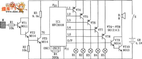
Touching eight-sound five-flash dynamic toy circuit diagram is shown in the diagram. It consists of HFC3018 module, and it can generate eight kinds ofdifferent voices: like step gunfire, aviation gunfire, game sight, telephone sight, bomb 1, bomb 2 sound, machine guns 1 sound and machine guns 2 sound, at the same time, itcan drive five small bulbs shining in an order.
(View)
View full Circuit Diagram | Comments | Reading(2709)
Multi-function program-controlled flash integrated circuit composed of CD71061
Published:2011/11/4 1:49:00 Author:May | Keyword: Multi-function , program-controlled , flash integrated circuit
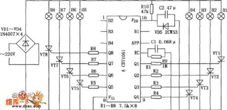
Multi-function program-controlled flash integrated circuit is shown in the diagram. It can ordinal display six basic patterns, namely elastic shrinkage, full light withinterval flash,negativeflowing to left with water, positiveflowing to the right with water, and meanwhile bright in left turn. This six basix patterns can be circularly displayed, and the cricularly times is controlled.
(View)
View full Circuit Diagram | Comments | Reading(2149)
Mood lantern controlling circuit (WT8089)
Published:2011/11/9 20:08:00 Author:May | Keyword: Mood lantern controlling
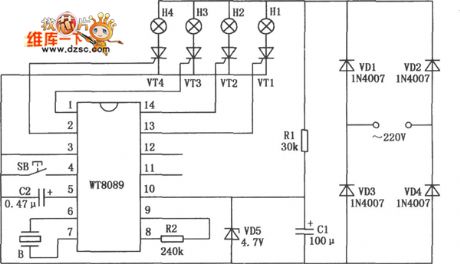
It can play eight electronic music and sixteent colorful light. Colorful flashing light and fine music can generate good audience effect. The jumping type of colorful light can becontrolled by function controlling buttons' pressing times to display sixteen different flashing kinds. They are turning right for horse racing, turning leftfor horse racing,turning on in the order, turning off in the order, double lights flowing moving, neighboring double light moving rolling, interval double lamps chasing, four lights flashing ar the same time, single lamp ordinal dithering, single lamp reverse dithering, double lights flashing, adjacent double lamps dithering chasing, double lamps reverse jitter flashing, interval double lamps jitter jumping, interval double lamps reverse jitter and four lights flashing and jitte.
(View)
View full Circuit Diagram | Comments | Reading(1316)
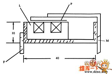
Metering circuit using PbS, PbSe
Published:2011/11/11 2:05:00 Author:May | Keyword: Metering, PbS, PbSe

This circuit canbeused for detecting infrared light, for example, it is used for detecting infrared band light signal in spectrophotometer. Amplifier output voltage Vo=Is·Rd·Rf/Ri (1)wherein : Is-signal current; Rd-optical detector essential resistance Dector can bemade by lead sulphide (PbS) or lead selenide (PbSe), and at room temperature, PbS response wave length range is 1.0~3.5µm, PbSe reponse wave length can reach 4.5µm. (ZhuXiaosong)
(View)
View full Circuit Diagram | Comments | Reading(2070)
| Pages:386/2234 At 20381382383384385386387388389390391392393394395396397398399400Under 20 |
Circuit Categories
power supply circuit
Amplifier Circuit
Basic Circuit
LED and Light Circuit
Sensor Circuit
Signal Processing
Electrical Equipment Circuit
Control Circuit
Remote Control Circuit
A/D-D/A Converter Circuit
Audio Circuit
Measuring and Test Circuit
Communication Circuit
Computer-Related Circuit
555 Circuit
Automotive Circuit
Repairing Circuit