
Circuit Diagram
Index 396
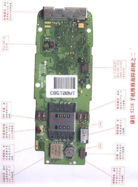
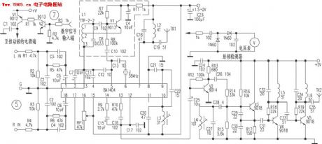
Konka 5218 repairing diagram 2
Published:2011/11/29 1:46:00 Author:Ecco | Keyword: Konka , repairing diagram
View full Circuit Diagram | Comments | Reading(866)
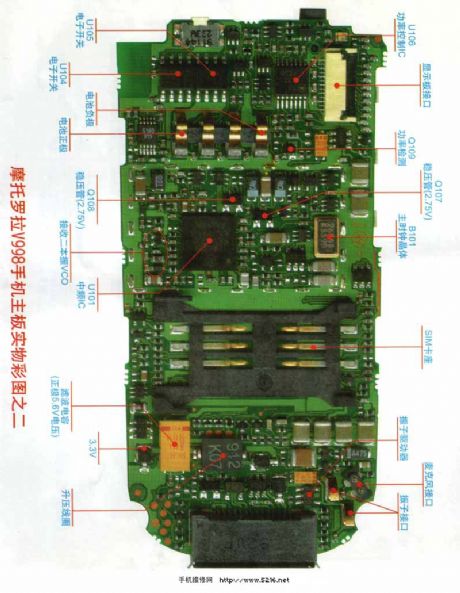
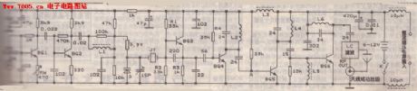
Motorola V998 repairing circuit diagram 2
Published:2011/11/29 1:45:00 Author:Ecco | Keyword: Motorola, repairing
View full Circuit Diagram | Comments | Reading(821)
IC AM radio circuit
Published:2011/11/28 21:45:00 Author:Ecco | Keyword: IC, AM radio


The receiver ( Figure a) input circuit is supplied by the 60Ω generator. Low -pass filter allows the entire frequency range with uniform sensitivity . Figure b shows the receiver input circuit coupled with transmitter inductive (Ri = 60Ω). Figure c shows the input circuit with ferrite ferrite antenna, the antenna structure is shown in Figure (d).
(View)
View full Circuit Diagram | Comments | Reading(3389)
usb switching to 232 circuit
Published:2011/11/28 21:37:00 Author:Ecco | Keyword: usb , switching to 232

View full Circuit Diagram | Comments | Reading(684)
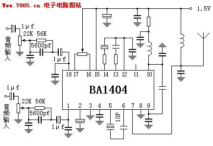
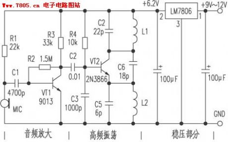
6w FM power amplifier circuit ( English)
Published:2011/11/11 2:17:00 Author:Ecco | Keyword: 6w , FM power amplifier


Assemble by soldering the components to the pads indicated. Keep coil, resistor, and capacitor leads as short as possible. The coils should be 3/16 to 1/4 above the board and separate turns by one wire diameter. Bend leads to form a little mounting foot for soldering to the circuit board. Tuning and power output are affected by the distance between the coil turns, you can make fine adjustments by either spreading or compressing the coil slightly. The area surrounding the pads is ground. C2, C3, C4, C6, C7, C8, C9, C10, L2, and R1 are soldered at one end to ground as well as the shield braid on the coax cables. Bolt Q1 to a small heat sink or the chassis with heat sink thermal compound or gray thermal pad underneath the tab. With an input level of 200-500mw, you should see an output of 5-6 watts. Be sure to have a proper dummy load (50 ohms) or tuned antenna connected to the output, doing otherwise will likely destroy the transistor.
(View)
View full Circuit Diagram | Comments | Reading(2716)
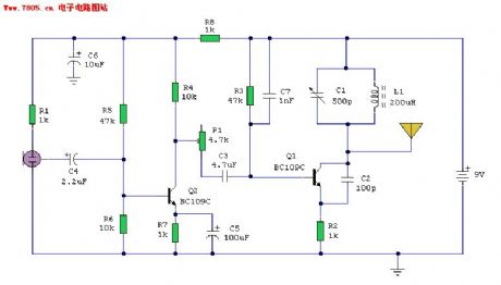
The whole FM transmitter circuit
Published:2011/11/28 21:37:00 Author:Ecco | Keyword: FM transmitter

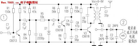
View full Circuit Diagram | Comments | Reading(1171)
45MHz FET oscillator circuit
Published:2011/11/28 0:57:00 Author:Ecco | Keyword: 45MHz , FET oscillator

The circuit's quartz crystal is between the source and drain of field effect transistor. The operating point is determined by the source resistor. Inductor and capacitor form a series resonant circuit.
(View)
View full Circuit Diagram | Comments | Reading(1646)
The crystal oscillator circuit with frequency in 2MHz
Published:2011/11/28 0:53:00 Author:Ecco | Keyword: crystal oscillator , 2MHz

Figure (a) and (b) show the two 2MHZ basic oscillator circuits. According to the circuit structure, it can adjust its best operating point by testing.
(View)
View full Circuit Diagram | Comments | Reading(2252)
Logarithmic sweep voltage controlled oscillator
Published:2011/11/28 0:31:00 Author:Ecco | Keyword: Logarithmic, sweep , voltage controlled oscillator

View full Circuit Diagram | Comments | Reading(1132)
The sine wave oscillator using LM386
Published:2011/11/24 20:49:00 Author:Ecco | Keyword: sine wave oscillator
The chart shows the sinusoidal oscillator circuit using LM386; the circuit uses the Wien bridge oscillator method, and the distortion factor of output signal of is very low. Small bulb H and resistor R3 form the negative feedback circuit, which makes sure that the signal amplitude output by oscillator is stable and has low distortion. When the capacitors C1, C2 values are the same , and they use the icon data, the sinusoidal frequency is 1KHz. When it is in actual production , H can select 3V, 15mA small bulb.
(View)
View full Circuit Diagram | Comments | Reading(2192)
Triangle wave - square wave generator circuit
Published:2011/11/24 20:53:00 Author:Ecco | Keyword: Triangle wave , square wave , generator
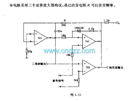
The circuit is composed of 3 operational amplifiers, and changing resistor R can change the frequency.
(View)
View full Circuit Diagram | Comments | Reading(1274)
Parallel resonant crystal oscillator composed of Gate circuit
Published:2011/11/27 20:28:00 Author:Ecco | Keyword: Parallel resonant , crystal oscillator , Gate circuit

When the quartz crystal under the action of the applied voltage, it will produce a piezoelectric effect, then the quartz crystal produces the mechanical vibrations, when the frequency of the applied voltage and crystal's natural oscillation is the same, the crystal 's mechanical amplitude is the largest and the alternating electric field will be largest to form piezoelectric resonator. The reactance frequency characteristics of quartz crystal reactance show that it has two closed resonance volume ratio, one is the series resonant frequency , the other one is parallel resonant frequency , when the crystal is in series resonance, the reactance is minimum, when it is in parallel resonance, the reactance is maximum, when it is between two frequency ranges, the crystal shows inductive , when it is free from two frequency ranges, the crystal shows capacitive.
(View)
View full Circuit Diagram | Comments | Reading(3451)
The pulse generator circuit with sharp pulse and sawtooth pulse
Published:2011/11/27 21:05:00 Author:Ecco | Keyword: pulse generator , sharp pulse , sawtooth pulse

The upper limit of the two pulses' frequency generated by the gate circuit is 5MHZ, the lower limit depends on the size of the capacitor . Sharp pulse width is about 50ns, which is output directly from TTL and non gate; sawtooth pulse is generated by impedance converter, which is a Schmitt trigger with high input impedance, so that it has a good sawtooth linearity . Gate device substitution : FLH731-49713S, FLH491-49702.
(View)
View full Circuit Diagram | Comments | Reading(968)
The pulse generator ( Figure 1.6 ) circuit with output multiple waveforms
Published:2011/11/27 20:49:00 Author:Ecco | Keyword: pulse generator , multiple waveforms

It uses the programmable unijunction transistor Th to form a pulse waveform generator circuit which can output multiple waveforms. Figure (b) shows the pulse waveforms output by a, b, c, d points which are shown in Figure (a) circuit. In this case, UB = 50V, pulse frequency f = 1000Hz, pulse peak U = UP = 20V. Component parameters R1 = 0.164MΩ, R2 = 0.256MΩ, R3 = 4.9MΩ, R4 or R5 = 8Ω, C = 410pF.
(View)
View full Circuit Diagram | Comments | Reading(1630)
The crystal oscillator with switch
Published:2011/11/24 21:30:00 Author:Ecco | Keyword: crystal oscillator , switch

View full Circuit Diagram | Comments | Reading(796)
Adjustable crystal oscillator
Published:2011/11/24 21:30:00 Author:Ecco | Keyword: Adjustable crystal oscillator

View full Circuit Diagram | Comments | Reading(821)
Crystal l00kHz interval calibration oscillator
Published:2011/11/27 20:42:00 Author:Ecco | Keyword: Crystal , l00kHz , interval calibration , oscillator

View full Circuit Diagram | Comments | Reading(673)
Transistor- FET transistor oscillator
Published:2011/11/27 20:41:00 Author:Ecco | Keyword: Transistor, FET transistor , oscillator

View full Circuit Diagram | Comments | Reading(987)
The audio signal generator circuit with low output resistance
Published:2011/11/28 21:01:00 Author:Ecco | Keyword: audio signal generator, low output resistance
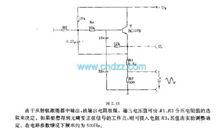
As it is output from the emitter follower, the output resistance is very low. Output voltage can be decided by R1, R2 piezoelectric resistance. If you want to get sinusoidal signal without distortion, you can access resistor R3, its value is determined by the test adjustment. In the case of parameters, the frequency of the circuit is about 500Hz.
(View)
View full Circuit Diagram | Comments | Reading(1136)
The power circuit of CASPER TM-5159 VGA color display
Published:2011/12/7 20:33:00 Author:Ecco | Keyword: power circuit , CASPER , VGA , color display

View full Circuit Diagram | Comments | Reading(778)
| Pages:396/2234 At 20381382383384385386387388389390391392393394395396397398399400Under 20 |
Circuit Categories
power supply circuit
Amplifier Circuit
Basic Circuit
LED and Light Circuit
Sensor Circuit
Signal Processing
Electrical Equipment Circuit
Control Circuit
Remote Control Circuit
A/D-D/A Converter Circuit
Audio Circuit
Measuring and Test Circuit
Communication Circuit
Computer-Related Circuit
555 Circuit
Automotive Circuit
Repairing Circuit