
Circuit Diagram
Index 393
T, R-40 Series of universal ultrasonic transmitting, receiving sensor circuit diagram
Published:2011/9/16 1:02:00 Author:Rebekka | Keyword: ultrasonic transmitting, receiving sensor
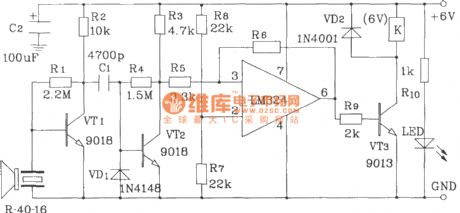
T/R-40 series of ultrasonic sensors works by piezoelectric effect. Usually we also call it transducer. This type of transducer is suitable for anti-theft alarm and remote.
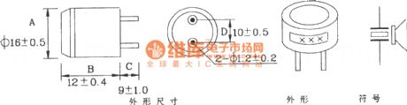
The shape, size and circuit symbols of T/R-40-XX series of ultrasonic sensors.
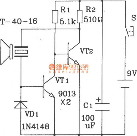
The ultrasonic transmitter circuit composed of discrete structure.
T/R-40-16 will emit a string of 40kHz ultrasonic signals. The circuit voltage is 9V, operating current is 25mA, control distance can up to 8m.
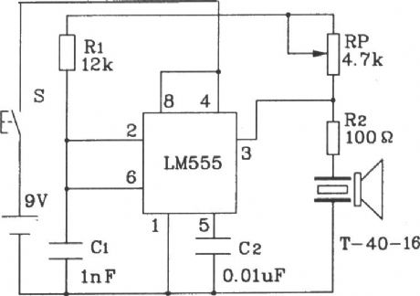
Ultrasonic transmitter circuit composed of 555.
The 40kHz oscillation pulse drives T-40-16 output from 555 of the pin 3, that makes it emit 40kHz ultrasonic signal. Circuit voltageis 9V, operating currentis 40 ~ 45mA, the control distance is more than 8m.
Bistable ultrasonic receiver circuit
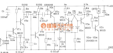
Universal ultrasonic receiver circuit. (View)
View full Circuit Diagram | Comments | Reading(5279)
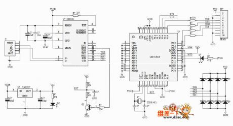
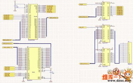
C8051F EC2 JTAG emulator circuit diagram
Published:2011/12/9 0:50:00 Author:Ecco | Keyword: JTAG emulator
View full Circuit Diagram | Comments | Reading(2161)
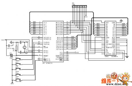
CD-ROM interface schematic circuit diagram
Published:2011/12/9 0:49:00 Author:Ecco | Keyword: CD-ROM interface , schematic
View full Circuit Diagram | Comments | Reading(3054)
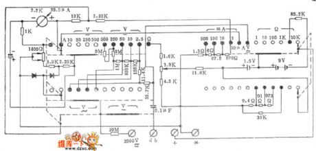
The high-performance 500 multimeter circuit diagram
Published:2011/12/9 0:49:00 Author:Ecco | Keyword: high-performance , multimeter
View full Circuit Diagram | Comments | Reading(1028)
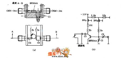
4GHZ oscillator circuit diagram composed of BFR34A transistor
Published:2011/12/8 20:21:00 Author:Ecco | Keyword: 4GHZ, oscillator, transistor

View full Circuit Diagram | Comments | Reading(1532)
Small FM transmitter (wireless speaker ) circuit diagram
Published:2011/12/9 1:30:00 Author:Ecco | Keyword: Small , FM transmitter, wireless speaker
View full Circuit Diagram | Comments | Reading(1771)
Small electronic coupling oscillator circuit diagram
Published:2011/12/8 20:23:00 Author:Ecco | Keyword: Small , electronic coupling oscillator

View full Circuit Diagram | Comments | Reading(940)
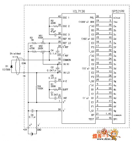
The LCD digital thermometer circuit using 7136
Published:2011/12/8 20:43:00 Author:Ecco | Keyword: LCD digital thermometer
View full Circuit Diagram | Comments | Reading(1509)
Active servo power amplifier circuit for lifting subwoofer
Published:2011/12/8 20:46:00 Author:Ecco | Keyword: Active servo , power amplifier , lifting subwoofer

View full Circuit Diagram | Comments | Reading(3127)
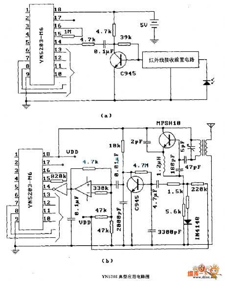
YN 5203 ( anti-theft system) radio or infrared remote control decoding circuit diagram
Published:2011/12/8 20:49:00 Author:Ecco | Keyword: anti-theft system, radio , infrared , remote control , decoding
View full Circuit Diagram | Comments | Reading(2032)
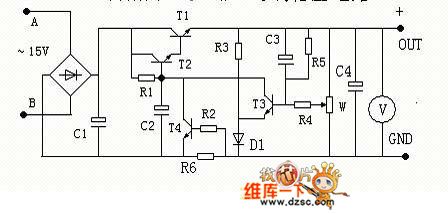
Adjustable voltage-stabilizing circuit with current limiting protection function
Published:2011/12/8 20:51:00 Author:Ecco | Keyword: Adjustable , voltage-stabilizing circuit , current limiting, protection function
View full Circuit Diagram | Comments | Reading(755)
Several vi transformation and constant current source circuits
Published:2011/12/8 20:19:00 Author:Ecco | Keyword: Several vi transformation , constant current source

View full Circuit Diagram | Comments | Reading(1581)
Memory internal memory circuit diagram
Published:2011/12/8 20:20:00 Author:Ecco | Keyword: Memory , internal memory
View full Circuit Diagram | Comments | Reading(770)
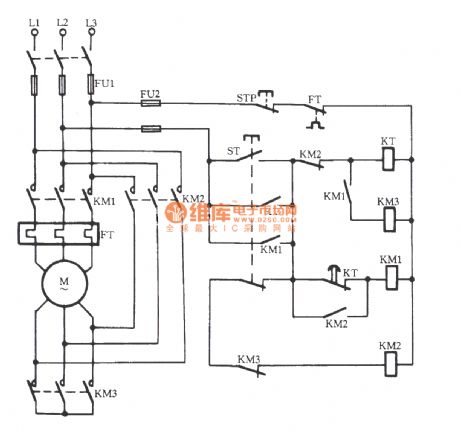
The Y-△ starting circuit 3 for motor without power switch
Published:2011/11/3 2:06:00 Author:Ecco | Keyword: Y-△ starting , motor , without power switch
View full Circuit Diagram | Comments | Reading(650)
The power circuit of COMPAQ 1504 TTL color monitor
Published:2011/12/8 0:57:00 Author:Ecco | Keyword: power circuit , COMPAQ , TTL , color monitor

View full Circuit Diagram | Comments | Reading(820)
The power circuit of COMPAQ TE-1420Q VGA multi-frequency monitor
Published:2011/12/7 20:34:00 Author:Ecco | Keyword: power , COMPAQ, VGA , multi-frequency monitor

View full Circuit Diagram | Comments | Reading(1024)
JJ2B-30 ~ 90 Variable voltage start-up circuit
Published:2011/12/7 2:08:00 Author:Ecco | Keyword: Variable voltage, start-up circuit
View full Circuit Diagram | Comments | Reading(595)
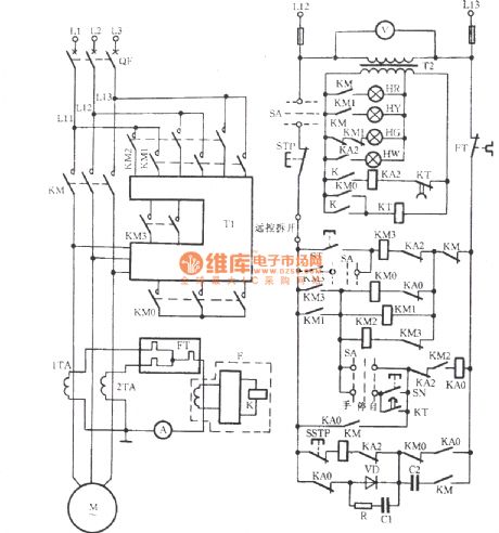
JJ28-11 ~ 22 Variable voltage start-up circuit
Published:2011/12/7 2:11:00 Author:Ecco | Keyword: Variable voltage , start-up
This starter is suitablefor 11 ~ 22kW motor.Because the current islarge,it uses three current transformers E to provide mutual inductance current.
(View)
View full Circuit Diagram | Comments | Reading(656)
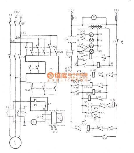
JJ1B-75 Autoformer step-down start circuit
Published:2011/12/7 2:12:00 Author:Ecco | Keyword: Autoformer, step-down start
View full Circuit Diagram | Comments | Reading(623)
LOGO module controlling autotransformer step-down start circuit
Published:2011/12/7 2:06:00 Author:Ecco | Keyword: LOGO module , controlling , autotransformer , step-down start

View full Circuit Diagram | Comments | Reading(1285)
| Pages:393/2234 At 20381382383384385386387388389390391392393394395396397398399400Under 20 |
Circuit Categories
power supply circuit
Amplifier Circuit
Basic Circuit
LED and Light Circuit
Sensor Circuit
Signal Processing
Electrical Equipment Circuit
Control Circuit
Remote Control Circuit
A/D-D/A Converter Circuit
Audio Circuit
Measuring and Test Circuit
Communication Circuit
Computer-Related Circuit
555 Circuit
Automotive Circuit
Repairing Circuit