
Circuit Diagram
Index 1816
The digital display answering racer circuit
Published:2011/6/7 11:52:00 Author:qqtang | Keyword: digital display, answering racer


In the figure, the digital display answering racer adapts the digital pipe as the display, which can make players and audiences see the results, so the transparence is good.Working principles: digital display answering racer circuit is shown in the figure. CD4511 is main part of the digital display answering racer. This is a BCD-7 lock/decoder/drive circuit, whose 1, 2, 6 and 7 pins are the input terminal, and 9~15 pins are the display output terminals. 3-pin LT is the detection terminal, when it is 0 , the output is 1 .
(View)
View full Circuit Diagram | Comments | Reading(610)
The digit display patient alarm device circuit
Published:2011/6/7 21:09:00 Author:qqtang | Keyword: digit display, patient alarm device

The circuit is shown in the figure, which can fulfill the dual-way signal delivering between sickrooms and duty rooms. The key switches K0~K9 and LED D0~D9 are installed in the sickroom, and the digital pipe and buzzer are fixed in the duty room. The buzzer will be still if there is no call from the sickroom, and the digital pipe is OFF. When patients press the switch K2, the buzzer in the duty room is buzzing and the pipe is indicating 2 ; at the same time, the LED in the sickroom is glowing, which shows that the patient signal has been delivered to the duty room. (View)
View full Circuit Diagram | Comments | Reading(700)
SC-MC-3--the microcomputer integrated circuit of electric music instrument single chip
Published:2011/6/7 21:20:00 Author:qqtang | Keyword: integrated circuit, electric music instrument


1.function featuresSC-MC-3 contains the clock oscillator circuit, reset circuit, key scanning pulse generating circuit, key order signal encoding circuit, data signal input/output connector circuit, screen signal decoding and drive circuit, and other additional function circuit, etc.2.pin functionsSC-MC-3 is in 42-pin dual in-line plastic package, whose pin arrangement is shown in the figure, and the pin functions are listed in the table.
The pin arrangement of SC-MC-3 The pin functions of SC-MC-3
(View)
View full Circuit Diagram | Comments | Reading(769)
SBX1765-01--the integrated circuit of the thick film comb filter
Published:2011/6/7 21:37:00 Author:qqtang | Keyword: integrated circuit, thick film


SBX1765-01 is an integrated circuit of the thick film comb filter produced by SONY, which is used in cores of Chanhong NC-3 large screen color TV .1.function featuresSBX1765-01 includes the A/D converter CXD1176Q, D/A converter CXD117Q, two 1H (NTSC) or 2H(PAL) time delay selectable wire CXK1202 and a digital dynamic comb filter CXCD2011. Its internal circuit is shown in the figure.
2. Pin functions and dataSBX1765-01 is in 30-pin thick film dual in-line package, whose pin functions and data are listed in the table.
(View)
View full Circuit Diagram | Comments | Reading(2173)
SAA7345GP--the CD digital signal process integrated circuit
Published:2011/6/7 21:45:00 Author:qqtang | Keyword: digital signal process, integrated circuit


SM7345GP is a CD digital signal process integrated circuit produced by Philips, which is widely used in all makes of disc players.1.function featuresSAA7345GP includes the reset circuit, clock oscillator circuit, motor control circuit, data connector circuit, read/write control circuit, DAC process circuit, RF signal process circuit and other control and additional circuit.2.pin functions and dataSAA7345GP is in 44-pin square package, whose pin functions and data are listed in the table.
(View)
View full Circuit Diagram | Comments | Reading(2066)
SAA7185--the video encoding and D/A converter integrated circuit
Published:2011/6/7 21:56:00 Author:qqtang | Keyword: D/A converter, integrated circuit


SAA7185 is a mass CMOS video encoding and D/A converter integrated circuit produced by Philips, which is widely used in all kinds of local and imported VCD players.1.function featuresSAA7185 is used to switch digit YUV signal back into analog TV signals by D/A converters according to PAL and NTSC mode. Its internal circuit is shown in the figure.The internal circuit of SAA7185
2.pin functions and dataSAA7185 is in 68-pin square package, whose pin functions and data are listed in the table.
(View)
View full Circuit Diagram | Comments | Reading(588)
SAA4991--the scanning converter integrated circuit
Published:2011/6/7 22:06:00 Author:qqtang | Keyword: scanning converter, integrated circuit


1.functions featuresSAA4991 includes the Y and UV signal process circuit, UV and Y storage circuit, vector process circuit, field Y and UV signal process circuit, test circuit, storage read-allowed control circuit, SNERT data clock signal process circuit and other additional circuit, whose internal circuit is shown in the figure.
The internal circuit of SAA49912.pin functions and dataSAA4991 is in 84-pin square package, whose pin functions and data are listed in the table.Pin functions and data of SAA4991
(View)
View full Circuit Diagram | Comments | Reading(658)
The inverter circuit diagram 1
Published:2011/6/3 2:16:00 Author:Lucas | Keyword: inverter
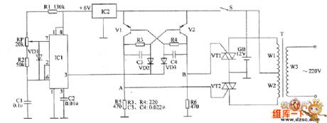
The inverter circuit consists of non-steady-state multivibrator, bistable flip-flop and switch output circuit, the circuit is shown as the chart. Astable multivibrator circuit is composed of time-base integrated circuit IC1, voltage regulator integrated circuit IC2 , resistors R1, R2, potentiometers RP, diode VD1 and capacitors C1, C2. Bistable trigger circuit consists of transistors V1, V2, resistors R3 ~ R6, capacitors C3, C4 and diodes VD2, VD3. Switch output circuit consists of thyristors VT1, VT2 and transformer T. After the power switch S is turned on, one road of the +12 V voltage of battery GB can directly povide power supply for bistable trigger, the other road is stabilized as +6 V for the astable multivibrator circuit.
(View)
View full Circuit Diagram | Comments | Reading(1257)
Electronic rodent repeller circuit diagram 3
Published:2011/6/3 2:15:00 Author:Lucas | Keyword: Electronic rodent repeller

The electronic rodent repeller circuit is composed of the astable multivibrator, emitter follower converter, voltage controlled oscillator (YC0), driver amplifier circuit and the piezoelectric ceramic speaker HA with super loudness, and the circuit is shown as the chart. Astable multivibrator integrated circuit is composed of the time-base integrated circuit IC1, resistors R1 ~ R3, capacitor C1 and so on. Emitter follower converter is composed of the transistor V and the bias components. Voltage-controlled oscillator (VCO) consists of the PLL IC IC2 and external RC components. Driver amplifier uses TWH68 special amplifier module (including power amplifier circuit and ferrite step-up transformer, etc.). R1 ~ R7 select 1/4W carbon film or metal film resistors resistors.
(View)
View full Circuit Diagram | Comments | Reading(835)
The interface circuit diagram between MSP430F413 and MFRC522
Published:2011/6/3 2:15:00 Author:Lucas | Keyword: interface
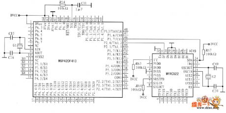
It sets theMSP430F413 as the example, and it uses I2C interfaces. The circuit is shown in Fig. Because the SCM MSP430F413 has no the port line with interface function being similar to I2C,it usesI / 0 simulation I2C timing sequence.
(View)
View full Circuit Diagram | Comments | Reading(3443)
Atlantis electromagnetic cooker circuit
Published:2011/6/5 22:11:00 Author:John | Keyword: electromagnetic cooker
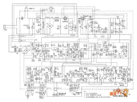
Atlantis electromagnetic cooker circuit is shown in the following.
(View)
View full Circuit Diagram | Comments | Reading(1084)
RSQ020N03、RSQ035N03、RSQ045N03 internal circuit
Published:2011/6/7 0:23:00 Author:John

RSQ020N03、RSQ035N03、RSQ045N03 internal circuit is shown in the following.
(View)
View full Circuit Diagram | Comments | Reading(445)
555 internal circuit
Published:2011/6/7 0:22:00 Author:John

555 internal circuit is shown below.
(View)
View full Circuit Diagram | Comments | Reading(1741)
parallel digital tube scanning circuit (common cathode)
Published:2011/6/7 0:21:00 Author:John | Keyword: parallel digital tube
Parallel digital tube scanning circuit (common cathode) is shown in the following.
(View)
View full Circuit Diagram | Comments | Reading(656)
RSR025N03 internal circuit
Published:2011/6/6 23:42:00 Author:John

RSR025N03 internal circuit is shown in the following.
(View)
View full Circuit Diagram | Comments | Reading(445)
Panasonic induction cooker circuit (KY-P2N)
Published:2011/6/6 23:41:00 Author:John | Keyword: induction cooker
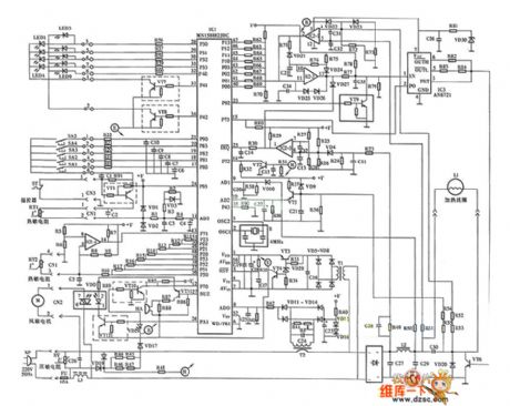
Panasonic induction cooker circuit (KY-P2N) is shown below.
(View)
View full Circuit Diagram | Comments | Reading(1668)
RSF014N03 internal circuit
Published:2011/6/7 0:30:00 Author:John

RSF014N03 internal circuit is shown in the following.
(View)
View full Circuit Diagram | Comments | Reading(453)
RSL020P03、RSQ025P03、RSQ030P03、RSQ035P03 internal circuit
Published:2011/6/7 0:30:00 Author:John

RSL020P03、RSQ025P03、RSQ030P03、RSQ035P03 internal circuit is shown below.
(View)
View full Circuit Diagram | Comments | Reading(490)
parallel LED digital tube static display circuit(total positive)
Published:2011/6/7 0:29:00 Author:John | Keyword: LED digital tube

Parallel LED digital tube static display circuit(total positive) is shown in the following.
(View)
View full Circuit Diagram | Comments | Reading(618)
TL494 400W power voltage regulator inverter circuit
Published:2011/6/7 0:28:00 Author:John | Keyword: voltage regulator inverter

TL494 400W power voltage regulator inverter circuit is shown in the following.
(View)
View full Circuit Diagram | Comments | Reading(7213)
| Pages:1816/2234 At 2018011802180318041805180618071808180918101811181218131814181518161817181818191820Under 20 |
Circuit Categories
power supply circuit
Amplifier Circuit
Basic Circuit
LED and Light Circuit
Sensor Circuit
Signal Processing
Electrical Equipment Circuit
Control Circuit
Remote Control Circuit
A/D-D/A Converter Circuit
Audio Circuit
Measuring and Test Circuit
Communication Circuit
Computer-Related Circuit
555 Circuit
Automotive Circuit
Repairing Circuit