
Circuit Diagram
Index 1819
The fabrication circuit of 3-pipe modulation wireless microphones
Published:2011/6/3 6:32:00 Author:Seven | Keyword: fabrication circuit, wireless microphone

View full Circuit Diagram | Comments | Reading(398)
The headphone circuit
Published:2011/6/3 0:10:00 Author:Seven | Keyword: headphone circuit

View full Circuit Diagram | Comments | Reading(462)
The AC charging circuit
Published:2011/6/2 6:48:00 Author:Seven | Keyword: charging circuit

(a) for the positive connection, AC power supply charges in positive half-circles
(b) for the negative connection, AC power supply charges in negative half-circles
(View)
View full Circuit Diagram | Comments | Reading(537)
The 3-phase AC voltage regulation circuit
Published:2011/6/2 6:41:00 Author:Seven | Keyword: 3-phase, voltage regulation

View full Circuit Diagram | Comments | Reading(808)
The telephone principle circuit (01)
Published:2011/6/2 22:56:00 Author:Seven | Keyword: principle circuit

View full Circuit Diagram | Comments | Reading(502)
The telephone principle circuit (02)
Published:2011/6/2 22:58:00 Author:Seven | Keyword: principle circuit

View full Circuit Diagram | Comments | Reading(619)
The telephone principle circuit (03)
Published:2011/6/2 22:57:00 Author:Seven | Keyword: principle circuit

View full Circuit Diagram | Comments | Reading(552)
The 555 DC raising pressure circuit
Published:2011/6/3 2:15:00 Author:nelly | Keyword: DC, raising pressure
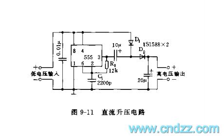
As shown on the figure 9-11, the astable multi-oscillation consists of the 555,R1 and C1. The oscillation frequency depends on the time constant of R1 and C1. The frequency shown on the figure is about 20kHz. The output voltage is about 2.2 times higher than the input DC voltage by dual voltage rectified. The load current can reach 50mA. It uses the bipolar 555. (View)
View full Circuit Diagram | Comments | Reading(597)
555 adjustable timer circuit for hours
Published:2011/6/2 4:01:00 Author:nelly | Keyword: adjustable timer

As shown in the figure 12-17, the circuit is composed of rectifier circuit, actable multivibrator IC1, count circuit IC2, unijunction oscillator and SCR AC switch. The rectifier circuit outputs 10V DC voltage, once the switch K is turned on, the CMOS type 555 starts to oscillate.
The oscillation frequency can be changed by adjusting RP1, it is continuously tunable from 0.1~1Hz.
IC2(CC4040) is a 12 bit binary serial counting/frequency divider. When the switch K is closed, due to the voltage of C9 can not suddenly changed, R terminal(11 foot) has a positive peak pulse voltage, it puts each trigger of CC4040 integrated block on 0 .
(View)
View full Circuit Diagram | Comments | Reading(1382)
The protector circuit of 555 full auto fridge
Published:2011/5/27 1:40:00 Author:Borg | Keyword: protector circuit
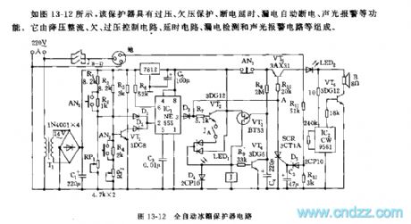
IC1(555),R1~R3,RP1,RP2 ,VT1 and so on consist a over/low voltage circuit. In the voltage range of 170V~240V, the 2-lead of IC1 is in a low voltage, which offsets 555, the output terminal of 3-lead is in a high LEV. Across D3 and R7, the LEV is imposed on VT2 base electrode, and it cooperates with the time delay circuit so that VT2 saturates and becomes conducting, J pulls in and Ja-d are getting through, then the outlet gets power. When the voltage is under 170V or over 240V, the 2-lead of 555 is in a high LEV, and the circuit is reset, the 3-lead is in a low LEV. The time delay circuit consist of VT3,VT4,R8,C4 and so on. (View)
View full Circuit Diagram | Comments | Reading(582)
555 simple automatic exposure circuit
Published:2011/5/24 2:51:00 Author:TaoXi | Keyword: simple, automatic, exposure circuit

As the figure 17-4 shows, this circuit is composed of a 555 and some resistance, capacitance components. The 555 is the monostable delay time circuit. If you press AN, the 555 sets, pin-3 has the high level voltage, the exposure light or the actuator turns on. The silicon photovoltaic cell suffers the illumination to produce the light current I, and this light current I charges C1, when C1's voltage is more than 2/3VDD, 555 circuit resets, pin-3 has the low level voltage, the exposure light or the actuator has no power to work. The threshold electrical level can be adjusted by RP1, the value is more than 1.4V.
(View)
View full Circuit Diagram | Comments | Reading(452)
555 water form color light control circuit
Published:2011/5/21 9:08:00 Author:TaoXi | Keyword: water form, color light, control circuit

As the figure 17-54 shows, the color light control circuit uses three 555 as the core, and the monostable circuit is composed of the 555, they control the SCR cycle conduction of different channels, so the color light turns on one by one, just like the water.
When the pin-3 of IC1 has the high level voltage, SCR1 conducts, the light turns on. At the same time, pin-3's high level voltage charges C3 through R3, when C3's voltage is higher than pin-6's threshold level 2/3VDD, IC2 sets and outputs the high level voltage, SCR2 conducts, the light turns on, at the same time it charges the C5. 555 is the bipolar type, the driving current is up to 150mA.
(View)
View full Circuit Diagram | Comments | Reading(427)
555 variable delay lighting auto off light circuit
Published:2011/5/21 7:58:00 Author:TaoXi | Keyword: variable, delay, lighting, auto off light

As the figure 17-36 shows, this circuit is composed of the step-down rectifier circuit, the boot timing circuit and the SCR control circuit, and it can be used in wide range of applications such as the floodlight of the staircases and corridors.
The step-down rectifier circuit's VDD=+9V, it supplies the DC current to the controller. The boot delay circuit is composed of the IC (555) and R1 ~ R4, C1, the monostable time depends on the position of the timing switch K. The delay time td=1.1RC1. When the delay time is over, 555 resets, SRC cuts off, the light bulb H automatic turns off. The delay time is between one minute to ten minutes and it depends on the time constant RC1.
(View)
View full Circuit Diagram | Comments | Reading(1150)
BA3416BL-the integrated dual preamplifier circuit
Published:2011/5/15 4:51:00 Author:Borg | Keyword: integrated, preamplifier circuit


BA3416BL is an integrated dual preamplifier circuit produced by Toyo Power Tool Corp., Japan, which is used in recorders and music centers.1.the internal circuit and pin functions of BA3416BLBA3416BL contains two lines of pre-amplifiers and logic controllers. Logic control circuit is to shift double-track head signal and shift the selecting circuit of metal straps and common straps.The internal circuit of BA3416BL is as shown in Figure 1. The IC is in 18-lead unilateral dual in-line package, whose pin functions and data are listed in Figure 1.
(View)
View full Circuit Diagram | Comments | Reading(2728)
BA3520-the integrated reproducing circuit of single door stereo
Published:2011/5/14 21:33:00 Author:Borg | Keyword: reproducing circuit, single door


BA3520 is an integrated reproducing circuit of low-voltage single door stereo reproducing produced by Toyo Corp., Japan, which is widely used in low-voltage walk-man and other low-voltage radios.the internal circuit and pin functions of BA3520BA3520 contains sub-circuits of dual head, dual power amplifier and power volume control, whose internal circuit and typical application circuit are listed in Figure 1. It is in flat 18-lead dual line package, whose pin functions and data are listed in Table 1.
Figure 1 the internal circuit and typical application circuit of BA3520F
(View)
View full Circuit Diagram | Comments | Reading(931)
BA3506A-the integrated reproducing circuit of single door stereo
Published:2011/5/15 1:07:00 Author:Borg | Keyword: integrated reproducing circuit, single door


BA3506A is an integrated reproducing circuit of single door stereo produced by Toyo Power Tool Corp., Japan, which is used in walk-man and stereos of same type as reproducing circuit.1.the internal circuit and pin functions of BA3506ABA3506A consists of two preset balance amplifier circuits of same functions and power amplifier circuits, whose internal circuit is shown in Figure 1. The IC is in 16-lead dual in-line plastic package, whose pin functions and data are listed in Table 1.2.main parameters of BA3506A
3.Typical application circuit of BA3506A
(View)
View full Circuit Diagram | Comments | Reading(1002)
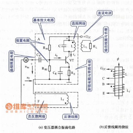
Transformer Coupling Oscillation Circuit
Published:2011/5/20 1:38:00 Author:Michel | Keyword: Transformer, Coupling Oscillation, Circuit
View full Circuit Diagram | Comments | Reading(461)
Dynatron Coupling Circuit
Published:2011/5/20 1:33:00 Author:Michel | Keyword: Dynatron Coupling, Circuit
View full Circuit Diagram | Comments | Reading(514)
Capacitance Three-point Concussion Circuit
Published:2011/5/20 1:45:00 Author:Michel | Keyword: Capacitance, Three-point, Concussion Circuit
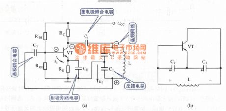
View full Circuit Diagram | Comments | Reading(420)
Single-chip Temperature Sensor Circuit
Published:2011/5/16 22:04:00 Author:Sharon | Keyword: Single-chip, Temperature Sensor
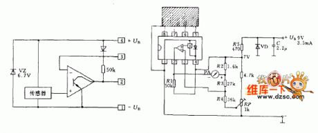
IC LM3911 is a silicon sensor constituted by the operational amplifier and constant voltage circuits. Just adding a small number of external components can form a simple electronic thermometer. There is transistor in the silicon used as sensitive device. Transistor base-emitter voltage changes with temperature. When the temperature rises, the base-emitter voltage is also increased. Temperature obtained from a copper block is delivered to the temperature sensor, in the condition that the copper block is linked to pin 5~8. These pins are internally connected to the temperature sensor. Temperature sensor constant voltage source (6.8V) provides power supply. Signals output from the temperature sensor is added to the input in the same direction with the internal operational amplifier, and its potential inverting input is fixed.Therefore, the potential of the operational amplifier output (Pin 2) is controlled by temperature sensor, with the meter indicating the reading.
Integrated chip in the circuit needs current about 3mA, and other 0.5mA current passes through the external circuit.
The operating temperature range of temperature sensor is -25 ℃ ~ +85 ℃. That indicates the scope is decided by external circuit parameters.
(View)
View full Circuit Diagram | Comments | Reading(502)
| Pages:1819/2234 At 2018011802180318041805180618071808180918101811181218131814181518161817181818191820Under 20 |
Circuit Categories
power supply circuit
Amplifier Circuit
Basic Circuit
LED and Light Circuit
Sensor Circuit
Signal Processing
Electrical Equipment Circuit
Control Circuit
Remote Control Circuit
A/D-D/A Converter Circuit
Audio Circuit
Measuring and Test Circuit
Communication Circuit
Computer-Related Circuit
555 Circuit
Automotive Circuit
Repairing Circuit