
Circuit Diagram
Index 1807
Field-effect transistor SP8M5、SP8M6、SP8M7、SP8M8、SP8M9 internal circuit
Published:2011/6/4 13:26:00 Author:John | Keyword: Field-effect transistor
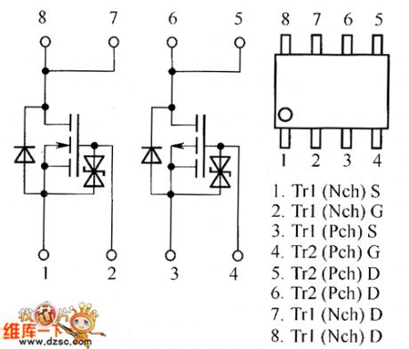
Field-effect transistor SP8M5、SP8M6、SP8M7、SP8M8、SP8M9 internal circuit is shown in the following.
(View)
View full Circuit Diagram | Comments | Reading(865)
Asymmetrical multivibrator circuit
Published:2011/6/4 13:25:00 Author:John | Keyword: Asymmetrical multivibrator
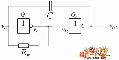
Asymmetrical multivibrator is the simplified form of symmetrical multivibrator [Figure 1]. This circuit only has a feedback resistor and a capacitive coupling. Feedback resistor forces static operating point to locate within the turning area of voltage transfer characteristics. That is to say that the static input level electricity is approximately equal to the output level electricity. So it is said that the static multivibrator is forced to work under the turning area of voltage transfer characteristics.
Feature1 Asymmetrical multivibrator circuit (View)
View full Circuit Diagram | Comments | Reading(497)
Telephone remote control circuit
Published:2011/6/4 13:18:00 Author:John | Keyword: Telephone remote control

Telephone remote control circuit is shown in the following.
(View)
View full Circuit Diagram | Comments | Reading(924)
Field-effect transistor STE110NS20FD、SFE180NE10、STE250NS10 internal circuit
Published:2011/6/4 13:16:00 Author:John | Keyword: Field-effect transistor
Field-effect transistor STE110NS20FD、SFE180NE10、STE250NS10 internal circuit is just shown in the following figure.
(View)
View full Circuit Diagram | Comments | Reading(633)
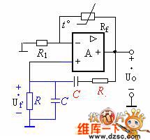
Electricity off and under-voltage automatical indicator protection circuit
Published:2011/6/4 12:51:00 Author:John | Keyword: automatical indicator

In this circuit, when the electricity is over the set upper limiting value of W1, LED2 lights. Door 2 locks to output 1 . J sucks and normally closed contacts break. Therefore, power failure protection can be temporarily achieved. When the electricity is under the set lower limiting value of W2, door 4 opens and LED1 lights. And door 3 outputs 0 so that J pulls. Power conservation can be again achieved. (View)
View full Circuit Diagram | Comments | Reading(600)
instrumentation amplifier with ±10 volt common mode range circuit
Published:2011/6/4 12:39:00 Author:John | Keyword: instrumentation amplifier

Instrumentation amplifier with ±10 volt common mode range circuit is just as shown below.
(View)
View full Circuit Diagram | Comments | Reading(491)
P87C766DT--the single chip microcomputer integrated circuit
Published:2011/6/8 21:56:00 Author:qqtang | Keyword: single chip, integrated circuit


1.function featuresP87C766DT contains the CPU, reset control circuit, clock oscillator circuit, remote order signal process circuit, I2C general control circuit, key order signal decoding circuit, demagnetizing circuit, stand by/start up control circuit, screen display letter generating and processing circuit, system control circuit and other control and additional function circuits, etc.2.pin functions and dataP87C766DT is in 42-pin dual line package, whose pin symbols and data are listed in the table.
(View)
View full Circuit Diagram | Comments | Reading(515)
RC bridge oscillator circuit
Published:2011/6/4 12:36:00 Author:John | Keyword: RC bridge oscillator
RC bridge oscillator circuit is just as shown in the figure. RC series-parallel network is connected to the output end and inverting input end of op-amp, aiming to form a positive feedback network with a frequency selective function. Besides, Rf and R1 are set within the op-amp's input end and its inverting input end. An integrated operational amplifier is connected with previous circuit to form a negative feedback amplifier circuit.
According to the following figure, the positive feedback circuit and negative feedback circuit form a Wien bridge circuit. And input and output terminals of the op-amp are connected across the bridge respectively. Therefore, this oscillation circuit is called RC bridge oscillator circuit.
(View)
View full Circuit Diagram | Comments | Reading(440)
PT2389--the preset balancer integrated circuit
Published:2011/6/9 7:16:00 Author:qqtang | Keyword: preset balancer, integrated circuit


1.function featuresPT2389 is a balancer of full functions. Apart from the modes of flat, rock, pop, classical and jazz that could be set, it also can strengthen effect of low-heavy sound and 3D sound, it has a total of 20 kind of tones. Besides, it contains high/low sound gain selector, selective unit, control unit, silence/mute, 3D sound effect and other circuits, whose internal circuit are shown in Figure 9-23(b). 2.pin functionsPT2389 is in 24-pin DIP package or SO package of paster.
(View)
View full Circuit Diagram | Comments | Reading(3312)
Electronic fence circuit
Published:2011/6/4 12:28:00 Author:John | Keyword: Electronic fence

Electronic fence circuit is just as shown below.
(View)
View full Circuit Diagram | Comments | Reading(1887)
PT2399--the digital reverberation integrated circuit
Published:2011/6/9 4:36:00 Author:qqtang | Keyword: digital reverberation, integrated circuit


1.function featuresPT2399 includes the sampling signal process circuit, reverberation comparing process circuit, microphone signal process circuit, clock oscillating circuit, digital reverberation preset amplifier circuit, reference power supply voltage circuit, power supply stable circuit, reverberation delay circuit and other additional function circuits, etc.2.pin functions and dataPT2399 is in 16-pin dual in-line plastic package, whose pin functions are listed in the table, and its working parameters are listed in the table.The pin functions of PT2399
(View)
View full Circuit Diagram | Comments | Reading(7902)
RTS501--the regulation timing integrated circuit
Published:2011/6/9 4:28:00 Author:qqtang | Keyword: regulation timing, integrated circuit


RTS501 is a regulation timing integrated circuit, which is suitable for the conditions that need speed regulation and timing, such as fan programme control and so on.1.function featuresRTS501 contains thetiming circuit, speed control circuit, clock oscillating circuit, speed control circuit and LED drive circuit, etc. It has functions of natural wind and sleep wind.2.pin functions RTS501 is in 18-pin dual line plastic package, whose outline and pin functions are shown in the figure.
The outline and pin functions of RTS5013. The typical application circuit
The typical application circuit of RTS501 (View)
View full Circuit Diagram | Comments | Reading(1305)
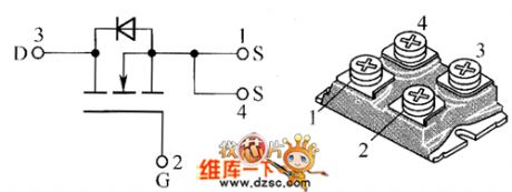
RDN050N20、RDN080N25、RDN100N20 internal circuit
Published:2011/6/9 4:52:00 Author:John

RDN050N20、RDN080N25、RDN100N20 internal circuit is shown below.
(View)
View full Circuit Diagram | Comments | Reading(630)
RDX03N60、RDX045N60、RDX050N50 internal circuit
Published:2011/6/9 4:36:00 Author:John

RDX03N60、RDX045N60、RDX050N50 internal circuit is shown below.
(View)
View full Circuit Diagram | Comments | Reading(556)
color monitor EMC EM-1428 type power supply circuit
Published:2011/6/9 4:35:00 Author:John | Keyword: color monitor

Color monitor EMC EM-1428 type power supply circuit is shown below.
(View)
View full Circuit Diagram | Comments | Reading(880)
RDX060N60、RDX080N50、RDX100N60、RDX120N50 internal circuit
Published:2011/6/9 4:33:00 Author:John

RDX060N60、RDX080N50、RDX100N60、RDX120N50 internal circuit is shown in the following.
(View)
View full Circuit Diagram | Comments | Reading(458)
SVGA color monitor ENVISION EC-1469 type power supply circuit
Published:2011/6/9 4:33:00 Author:John | Keyword: color monitor

SVGA color monitor ENVISION EC-1469 type power supply circuit is shown below.
(View)
View full Circuit Diagram | Comments | Reading(550)
T6668--the audio process integrated circuit
Published:2011/6/9 1:52:00 Author:qqtang | Keyword: audio process, integrated circuit


1. Function featuresThe internal circuit of T6668 consists of the microphone amplifier that is formed by CMOS backward amplifiers, the ADM separation/compound circuit which is responding to analog signal separation and digital signal compounding and D/A converting circuit; the clock that provide with address and control signal, counter and D/A (dynamic storage) connector, and portable transformer and band-pass filter which are used to improve the sound quality; the CPU connector for connecting computers conveniently, and other additional function circuits,etc.
(View)
View full Circuit Diagram | Comments | Reading(909)
power MOSFET gate drive constituted by the transistor and others circuit
Published:2011/6/9 4:31:00 Author:John | Keyword: transistor, power MOSFET gate drive

The circuit consists of two forward converters, for which one is the converter to charge the power MOSFET gate capacitor and the other is to discharge its gate capacitor. Recommended power supply voltage is from 12V to 15V. On the rising edge of the driving pulse, VT5 receives the pulse. Referring to given value for Cl and Rl in the figure, its typical duration is 2OOns. Then the pulse is transmitted to the secondary side of transformer Tl. When VT6 and VD3 are all given to a appropriate bias, the sub-pulse would charge the capacitor between the power MOSFET and the source pole. Afterwards, the current path is closed.
(View)
View full Circuit Diagram | Comments | Reading(2124)
RHK003N06、RHK005N06、RHP020N06、RHP030N03 internal circuit
Published:2011/6/9 4:19:00 Author:John

RHK003N06、RHK005N06、RHP020N06、RHP030N03 internal circuit is shown below.
(View)
View full Circuit Diagram | Comments | Reading(498)
| Pages:1807/2234 At 2018011802180318041805180618071808180918101811181218131814181518161817181818191820Under 20 |
Circuit Categories
power supply circuit
Amplifier Circuit
Basic Circuit
LED and Light Circuit
Sensor Circuit
Signal Processing
Electrical Equipment Circuit
Control Circuit
Remote Control Circuit
A/D-D/A Converter Circuit
Audio Circuit
Measuring and Test Circuit
Communication Circuit
Computer-Related Circuit
555 Circuit
Automotive Circuit
Repairing Circuit