
Circuit Diagram
Index 1802
The electric thermometer of LED display
Published:2011/6/4 0:22:00 Author:Seven | Keyword: electric thermometer

See as Figure 3.1, this is an electric thermometer circuit of LED display. The temperature sensor KTY10 has a good linear relationship between temperature and resistance, and it can be linked with the connecting points A and B of measuring display circuit with a 100m wire, the maximum range of the number display is from -50 to +150, the display bit is 3*1/2.
(View)
View full Circuit Diagram | Comments | Reading(1763)
The whole hotplate circuit (1)
Published:2011/6/3 8:37:00 Author:Seven | Keyword: hotplate circuit

View full Circuit Diagram | Comments | Reading(626)
The whole hotplate circuit (2)
Published:2011/6/3 8:37:00 Author:Seven | Keyword: hotplate circuit

View full Circuit Diagram | Comments | Reading(478)
The whole hotplate circuit (3)
Published:2011/6/3 8:38:00 Author:Seven | Keyword: hotplate circuit

View full Circuit Diagram | Comments | Reading(749)
The temperature data collecting system
Published:2011/6/4 0:14:00 Author:Seven | Keyword: temperature data

Notes: precision is 0.1%, 1% thin film resistance, Rplat is 1KΩ when it is 0℃.
Figure 1-4 the RID signal adjuster of digital linear plat resistance
The LT1027 in the circuit is a precise 5V parameter, and its temperature drifting is zppm/℃; the output source is 15mA, the lower is 10mA; the quick reaction is fabulous, which is used to input the parameter of A/D converters, and it is fixed with noise impedance pin; the long-term stabilization is good; when it is in the range of 0.1Hz~10Hz, the noise is lower than 1ppm.
(View)
View full Circuit Diagram | Comments | Reading(521)
The temperature compensation circuit
Published:2011/6/3 9:05:00 Author:Seven | Keyword: temperature compensation

Figure 1-95 The temperature compensation circuitThe KTY sensors in the circuit is fit for positive and negative temperature drifting compensation. Under many conditions, the KMZ10B temperature drifting is negative, and an OP-Amp, NE52300, is used to to complete the following functions:1.average (from sensor to sensor) sensitivity temperature drifting; 2.the potentiometers of R1 and R2 are used to adjust maladjustment;3.the potentiometer RT is used to adjust the gains.
(View)
View full Circuit Diagram | Comments | Reading(578)
The thermometer circuit
Published:2011/6/3 8:35:00 Author:Seven | Keyword: thermometer circuit

Notes: the circuit is fixed with a K thermal couple, the whole resistance is a 1% thin-film resistor. In the range of 0~60℃, the compensation precision of the cool pole is ±1℃. The temperature signal is output by another amplifier. LT0114 is a dual-four OP-Amp.Figure 1-75 the thermoelectric couple temperature circuit (View)
View full Circuit Diagram | Comments | Reading(493)
TC8835BN--the integrated circuit of the digital audio process
Published:2011/6/7 12:07:00 Author:qqtang | Keyword: integrated circuit, digital audio process


1. Function features TC8835BN mainly consists of the address counter, machine halt address storage, appendix register, dynamic storage connector circuit, clock oscillator circuit, time based generator control circuit, sound digit storage analyse/compound circuit, D/A counter voltage follower, state register, micro-process connector circuit and other additional function circuit, etc. It's internal circuit is shown in Figure 1.Figure 1. The internal circuit of TC8835BN
2.pin functions
(View)
View full Circuit Diagram | Comments | Reading(570)
The multi-Line answering racer circuit
Published:2011/6/7 11:22:00 Author:qqtang | Keyword: multi-Line answering racer

See as the figure, this is a multi-Line answering racer circuit, whose characters are as follows:(1) the number of lines is large, which can be added to 10 (there are 6 in the figure); (2) it is fixed with self-made digital large screen display team No., the image is direct, and the screen can be used for thousands of audiences; (3) it is adapted with the pulse scanning method, and there won't be more than one team answering at the same time; (4) quality-price ratio is high. The circuit is made of 3 CMOS integrated circuits and some common elements, which is low-cost.Elements selecting: IC1 is a 6 NAND CD4069. (View)
View full Circuit Diagram | Comments | Reading(508)
differential amplifier with light intensity change measurement circuit
Published:2011/5/23 22:46:00 Author:John | Keyword: light intensity change measurement

Figure (a) is a sensitive optical differential amplifier circuit. It has two identical photosensitive transistors (such as BPY62), being respectively connected to the op-amp 709 through its symmetry emitter follower BC107. Resistors R1 and R2 are determined according to the ambient brightness. Potentiometer RP2 can be used to adjust symmetry of two-input divider and operational amplifier. Potentiometer RP1 is used to adjust the amplification factor. The phototransistor base in this circuit opens. Figure (b) circuit has a good advantage of adapting to ambient light conditions.
(View)
View full Circuit Diagram | Comments | Reading(1670)
TC9012F--the remote control emitter integrated circuit
Published:2011/6/7 10:56:00 Author:qqtang | Keyword: remote control, integrated circuit


TC9012F is a remote control emitter integrated circuit produced by Toshiba, which is widely used in remote emitters of air-conditioners, TV sets, stereo equipment, disc players, etc.1.functions featuresTC9012F contains the key pulse generating circuit, key order encoding circuit, clock oscillating circuit, display drive circuit, customer number setting selector circuit, buffer amplifier circuit, test circuit and other additional function circuits.2.pin functions and dataTC9012F is in 20-pin dual line package.
(View)
View full Circuit Diagram | Comments | Reading(702)
TC9020P-003--the integrated circuit of letter display generators
Published:2011/6/7 10:45:00 Author:qqtang | Keyword: integrated circuit, letter display generator


TC9020P-003 is an integrated circuit of letter display generator produced by Toshiba, which is widely used in many makes of local and imported color TV.1. Function features TC9020P-003 includes clock oscillator circuit, data input connector circuit, horizontal/vertical field locating and blank signal process circuit, etc.2.pin functions and dataTC9020P-003 is in 16-pin dual in-line package, whose pin functions are shown in Figure 1, and its parameters are listed in Table 1.Figure 1. The pin functions of TC9020P-003
(View)
View full Circuit Diagram | Comments | Reading(640)
The caller number display device circuit
Published:2011/6/7 10:36:00 Author:qqtang | Keyword: caller number, display device

The device works with the phones that haven't got the functions of display, which can display caller number so that people can check if the called number is right.See as the circuit, the dialing generates DTMF signals and the signals are decoded by decoder CM8870P1(IC1), then the phone number BCD codes are generated, the BCD code of each number is locked in the according latch. This circuit can display 10 bit phone numbers. The first bit of the number is locked in IC5A(1/2CD4508), the second is locked in IC5B, etc. (View)
View full Circuit Diagram | Comments | Reading(692)
15W Triple Output DC / DC module power supply design circuit
Published:2011/5/24 0:05:00 Author:John | Keyword: DC / DC module power supply

DC / DC module has been widely used in railway communications, microwave communications, industrial control, marine electronics, avionics, ground radar, fire-fighting equipment and medical equipment, teaching equipment and many other fields. Many applications require multi-output, such as SCM intelligent controller. SCM needs power supply of 5V, while the op-amp usually needs power supply of 12V. During the design of multiple outputs, there are many different points from the single output. It is necessary to consider transformer pin constraints, multi-secondary transformer design and voltage regulator circuit achievement. It is also needed to consider the load rates for light load and full load of each channel and the characteristics for cross-load regulation.
(View)
View full Circuit Diagram | Comments | Reading(2335)
Practical constant current charger circuit
Published:2011/5/24 3:26:00 Author:John | Keyword: constant current charger

This circuit is actually a constant current source. Nuclear device is an integrated three-terminal adjustable regulator LM317T. Within the sufficient power supply voltage, LM317T can maintain a 1. 25V higher voltage of the + Vout than that of the ADJ. See the connection in the figure. The terminal end of ADJ is connected directly to rechargeable batteries. However, the internal resistance for ADJ terminal end is large (the current does not exceed 50μA under normal circumstances), so the circuit can be approximately regarded as an open circuit. But it can sample out of the voltage. If LM317T improves the voltage on the + Vout terminal end to be higher than that of ADJ terminal end of about 1.25V, the resistor cross-connected to the + Vout and ADJ can have the current of 1.25V/25.5Ω = 0. 05A = 50mA. (25.5Ω is the total resistance for the situation when R1 and R2 are parallel placed with the opening switch). Such current flows through the battery to charge the battery within a constant current.
(View)
View full Circuit Diagram | Comments | Reading(2435)
TC9020P-011--The letter display generating integrated circuit
Published:2011/6/7 10:21:00 Author:qqtang | Keyword: letter display generating, integrated circuit


TC9020P-011 is a letter display generating integrated circuit, which is widely used in many makes of local and imported color TV.1.function featuresTC9020P-011 contains the letter signal generating circuit, clock oscillating circuit, data input connector circuit, horizontal/vertical field locating and black signal process circuit, etc. 2.pin functions and dataTC9020P-011 is in 16-pin dual in-line package, whose pin functions are in Figure 1, and the working parameters are listed in Table 1.Figure 1. pins of TC9020P-011
(View)
View full Circuit Diagram | Comments | Reading(604)
The glowing digit circuit
Published:2011/6/7 2:42:00 Author:qqtang | Keyword: glowing digit

The working principle is as follows. N1~Nn are 9-bit micro digital switch, when being set, each switch can only links to 1 bit(1~9), others are cut off. When all 1~9 are cut off, it indicates 0 . For example, if the front 3-bit digital pipes of N1~N3 indicate 098 , then N1 is off, the 9th bit of N2 is on, the 8th bit of N3 is conducting; the other set method is the same. Among the screens, N1~Nn are 1.5 inch highly bright overcast pipes, which are corresponding to N1~Nn. (View)
View full Circuit Diagram | Comments | Reading(633)
electric bicycle quick charger circuit
Published:2011/5/25 20:08:00 Author:John | Keyword: electric bicycle, quick charger

The AC220V electricity is stepped-down through transformer T1 and is regulated through the full-wave rectifier D1-D4. Thus the charging circuit is supplied to work. Then the output end is correctly accessed to the set recharged bottle. If each half-wave peak value of the rectifier output ripple voltage is higher than the output voltage of the battery, the thyristor SCR is triggered to conduct by the Q collector current. The current charges the battery through the SCR. When the pulsating voltage is close to battery voltage, the SCR is off and charging process stops. Conduction voltage for transistor Q can be adjusted by the regulation of R4. The R4 is generally adjusted, from large value to small value, to trigger SCR. LED D5 in the figure is used for the power indicator and D6 is used for charging instructions. (View)
View full Circuit Diagram | Comments | Reading(1983)
TC9028P-012 and TC9028F-012 --The single chip remote emitter integrated circuit
Published:2011/6/7 2:12:00 Author:qqtang | Keyword: single chip, remote emitter
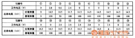
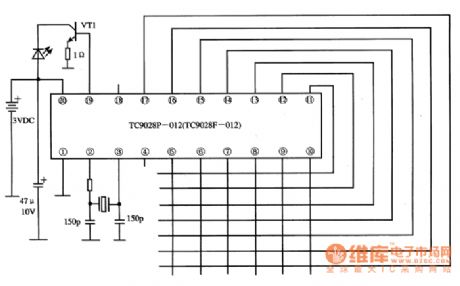
TC9028F-012 is the single chip remote emitter integrated circuit produced by Toshiba, which is widely used in systems of TV, stereos, disc players, air-conditioners and so on.1.function featuresTC9028F-012 contains the clock oscillator circuit, key scanning pulse generator, remote order encoder, signal emitting pre-amplifier circuit, measuring circuit and other additional circuit, etc.2.pin functions and dataTC9028F-012 is in 20-pin dual in-line package, whose pin functions are as follows:2-pin and 3-pin clock oscillating circuits connect with the element connectors.
(View)
View full Circuit Diagram | Comments | Reading(383)
back-up power supply automatic charger circuit
Published:2011/5/25 20:06:00 Author:John | Keyword: automatic charger

Backup power supply is temporary power supply equipment which is set in case of power failure or other reasons. Common ones are small back-up power generators and a variety of batteries. Among them, an economic and durable lead-acid storage battery is the first choice for back-up power supply. The authors have considered carefully designing an automatic battery charger for lead-acid batteries. The circuit is as shown in the figure (emitting the part that electricity is being bucked and rectified)
The core part of the circuit is composed by NE555 hysteresis comparator . R8, R9, RP1 and RP2 constitute sampling circuit and LED1-LED3 is an indicator for charging status. The charger of the battery is connected with an electrical relay, leading the cutting-off to be more reliable. S1 and S2 are touch switched, which are used to manually control the charging process. As a result, the circuit becomes more flexible and more convenient. (View)
View full Circuit Diagram | Comments | Reading(2855)
| Pages:1802/2234 At 2018011802180318041805180618071808180918101811181218131814181518161817181818191820Under 20 |
Circuit Categories
power supply circuit
Amplifier Circuit
Basic Circuit
LED and Light Circuit
Sensor Circuit
Signal Processing
Electrical Equipment Circuit
Control Circuit
Remote Control Circuit
A/D-D/A Converter Circuit
Audio Circuit
Measuring and Test Circuit
Communication Circuit
Computer-Related Circuit
555 Circuit
Automotive Circuit
Repairing Circuit