
Circuit Diagram
Index 1811
switching power supply constant current charger circuit
Published:2011/6/4 13:13:00 Author:John | Keyword: constant current charger

Switching power supply constant current charger circuit is shown below.
(View)
View full Circuit Diagram | Comments | Reading(4104)
variable gain and differential-input instrumentation amplifier
Published:2011/6/4 13:14:00 Author:John | Keyword: instrumentation amplifier

Variable gain and differential-input instrumentation amplifier is shown below.
(View)
View full Circuit Diagram | Comments | Reading(1971)
Quartz multivibrator circuit
Published:2011/6/4 13:15:00 Author:John | Keyword: Quartz multivibrator
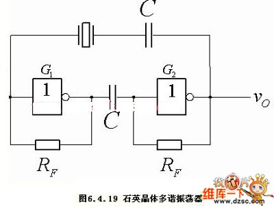
Figure: Quartz multivibrator circuit (View)
View full Circuit Diagram | Comments | Reading(606)
Field-effect transistor SP81、SP8K2、SP8K24 internal circuit
Published:2011/6/5 2:43:00 Author:John | Keyword: Field-effect transistor
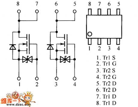
Field-effect transistor SP81、SP8K2、SP8K24 internal circuit is shown below.
(View)
View full Circuit Diagram | Comments | Reading(866)
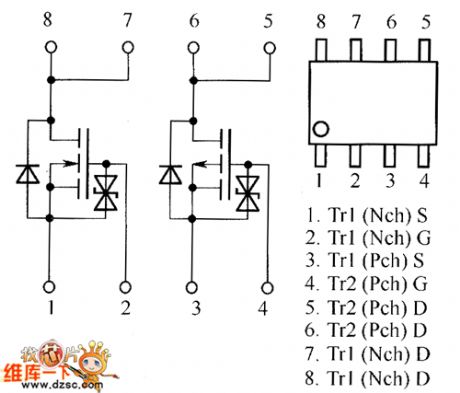
Field-effect transistor SP8J1、SP8J2、SP8J3、SP8J5 internal circuit
Published:2011/6/5 2:44:00 Author:John | Keyword: Field-effect transistor
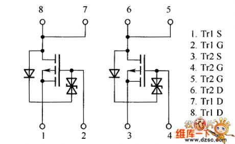
Field-effect transistor SP8J1、SP8J2、SP8J3、SP8J5 internal circuit is shown below.
(View)
View full Circuit Diagram | Comments | Reading(762)
Five-divider frequency circuit
Published:2011/6/5 2:52:00 Author:John | Keyword: Five-divider frequency
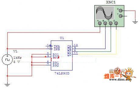
Figure: Five-divider frequency circuitWhen the counting pulse is input from the INB, the output would be QB, QC and QD. Such would form quinary counter (also called five-divider frequency circuit), whose circuit is just as shown in Figure 2-3. Use four-trace oscilloscope to record the output waveform. (View)
View full Circuit Diagram | Comments | Reading(453)
one switching-regulator circuit
Published:2011/6/4 13:28:00 Author:John | Keyword: switching-regulator

One switching-regulator circuit is shown in the following.
(View)
View full Circuit Diagram | Comments | Reading(1492)
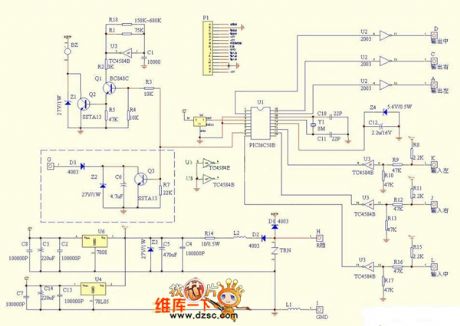
pic16c54 control Gree electronic sterilizer circuit
Published:2011/6/4 13:29:00 Author:John | Keyword: electronic sterilizer

pic16c54 control Gree electronic sterilizer circuit is shown in the following.
(View)
View full Circuit Diagram | Comments | Reading(1620)
Field-effect transistor SP8M10、SP8M2、SP8M21、SP8M24 internal circuit
Published:2011/6/4 13:30:00 Author:John | Keyword: Field-effect transistor
Field-effect transistor SP8M10、SP8M2、SP8M21、SP8M24 internal circuit is shown below.
(View)
View full Circuit Diagram | Comments | Reading(747)
Symmetric multivibrator circuit
Published:2011/6/4 23:59:00 Author:John | Keyword: Symmetric multivibrator
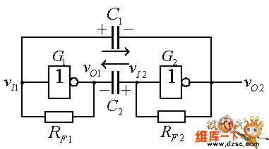
Figure: Symmetric multivibrator circuitMultivibrator is a self-oscillation circuit. Because there is no stable working state, multivibrator is also known as non-steady-state circuit. Specifically, if the multivibrator is at the state 0 at the very beginning, it would keep the state 0 for a period of time and then automatically run into state 1afterwards. If it remains state 1 for a period of time, it will automatically transfer to state 0. Such transfer would occur again and again, outputting the rectangular wave. (View)
View full Circuit Diagram | Comments | Reading(570)
Hainan Mazda parking sensor circuit
Published:2011/6/5 Author:John | Keyword: parking sensor
Hainan Mazda parking sensor circuit is shown below.
(View)
View full Circuit Diagram | Comments | Reading(2200)
Herald M810 amplifier system control circuit( two)
Published:2011/6/5 0:02:00 Author:John | Keyword: amplifier

Herald M810 amplifier system control circuit( two) is shown below.
(View)
View full Circuit Diagram | Comments | Reading(595)
RQA0004PXDQS、RQA0005QXDQA、RQA0008RXDQS internal circuit
Published:2011/6/8 9:39:00 Author:John

RQA0004PXDQS、RQA0005QXDQA、RQA0008RXDQS internal circuit is shown in the following.
(View)
View full Circuit Diagram | Comments | Reading(577)
HF-10A type electromagnetic cooker circuit
Published:2011/6/5 22:12:00 Author:John | Keyword: electromagnetic cooker

HF-10A type electromagnetic cooker circuit is shown in the following.
(View)
View full Circuit Diagram | Comments | Reading(862)
Single remote control (multi-coding) circuit
Published:2011/6/5 22:10:00 Author:John | Keyword: Single remote control

Single remote control (multi-coding) circuit is shown below.
(View)
View full Circuit Diagram | Comments | Reading(615)
Yonghua M0-88 type electromagnetic cooker circuit
Published:2011/6/5 22:08:00 Author:John | Keyword: electromagnetic cooker

Yonghua M0-88 type electromagnetic cooker circuit is shown below.
(View)
View full Circuit Diagram | Comments | Reading(682)
prolonging signal light battery life circuit
Published:2011/6/5 10:52:00 Author:John | Keyword: prolonging signal light

Use former two out of 4011 CMOS’s 4 non-door to constitute a chopper oscillator. And use a 1MΩ potentiometer to change the duty cycle. If the third non-door is not connected, it is helpful to apply the input end of the fourth non-door into the integrated circuit (14). Before the power is turned, the potentiometer is firstly transferred to the middle position and then is regulated. In order to prolong the original battery life of 3 times, 50% duty cycle should be provided signal light with intermittent signal current and double voltage.
(View)
View full Circuit Diagram | Comments | Reading(574)
Wanbao DC2-13 series type electromagnetic cooker circuit
Published:2011/6/5 10:45:00 Author:John | Keyword: electromagnetic cooker

Wanbao DC2-13 series type electromagnetic cooker circuit is shown in the following.
(View)
View full Circuit Diagram | Comments | Reading(964)
Suopu SP-200 type cooker circuit
Published:2011/6/5 10:20:00 Author:John | Keyword: cooker

Suopu SP-200 type cooker circuit is shown below.
(View)
View full Circuit Diagram | Comments | Reading(773)
SGVA color display FUJITSU FMV-DPS84Y2 type power supply circuit
Published:2011/6/5 3:53:00 Author:John | Keyword: color display

SGVA color display FUJITSU FMV-DPS84Y2 type power supply circuit is shown in the following.
(View)
View full Circuit Diagram | Comments | Reading(517)
| Pages:1811/2234 At 2018011802180318041805180618071808180918101811181218131814181518161817181818191820Under 20 |
Circuit Categories
power supply circuit
Amplifier Circuit
Basic Circuit
LED and Light Circuit
Sensor Circuit
Signal Processing
Electrical Equipment Circuit
Control Circuit
Remote Control Circuit
A/D-D/A Converter Circuit
Audio Circuit
Measuring and Test Circuit
Communication Circuit
Computer-Related Circuit
555 Circuit
Automotive Circuit
Repairing Circuit