
Circuit Diagram
Index 1808
Serial LED digital static display circuit
Published:2011/6/9 4:16:00 Author:John | Keyword: Serial LED digital
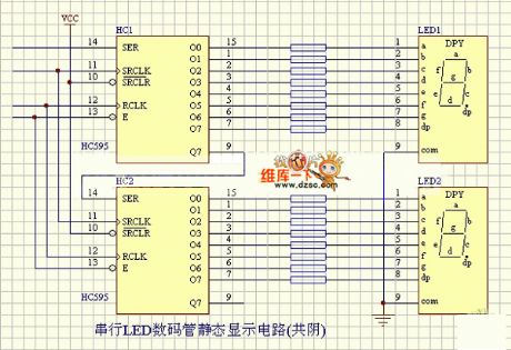
Serial LED digital static display circuit is shown below.
(View)
View full Circuit Diagram | Comments | Reading(625)
RQA0001DNS、RQA000DNS、RQA0003DNS internal circuit
Published:2011/6/9 4:07:00 Author:John

RQA0001DNS、RQA000DNS、RQA0003DNS internal circuit is shown below.
(View)
View full Circuit Diagram | Comments | Reading(641)
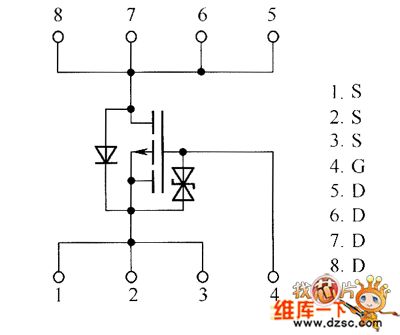
Field-effect transistor RTL035N03、RTQ020N03、RTQ035N03 internal circuit
Published:2011/6/5 3:24:00 Author:John | Keyword: Field-effect transistor
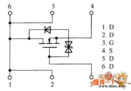
Field-effect transistor RTL035N03、RTQ020N03、RTQ035N03 internal circuit is shown in the following.
(View)
View full Circuit Diagram | Comments | Reading(625)
Auto-grain machine optical axis circuit
Published:2011/6/5 4:12:00 Author:John | Keyword: Auto-grain machine

Firstly, use mechanical ventilation to send the grain to food stored grain box at certain height through the pipeline. Then the grain would flow grain stored pipeline with controlled door to automatic platform meter. When the grain flows to a certain weight, automatic platform meter would deliver a signal. The implementation components work to shut off the food pipe valve. At this time, automatic weighing process ends.
In the figure, the photodiode 2CU2B is installed on the automatic platform meter to receive the signal outputs during the weighing process. Such signal depends on whether the status of meter’s shaft has covered signals from optical signal light source or not. Optical signals received by photodiode would be amplified through the line to control the relay. Then the implementation components are controlled to realize the purpose to automatically transfer grain. (View)
View full Circuit Diagram | Comments | Reading(544)
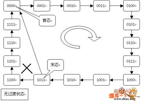
63 nary counter formed by cascade preset number circuit
Published:2011/6/5 5:16:00 Author:John | Keyword: 63 nary counter
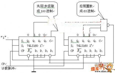
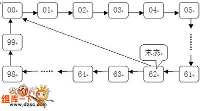
63 nary counter formed by cascade preset number circuit: We can also form 10i counter or 16i counter by the cascade method and use the preset method to constitute an arbitrary nary counter. 63 nary counter can be formed by 100 nary counter composed of two 10 nary counters (74LS160) and then can achieve the function by preset method. Its counting state transition is shown in Figure 2. It should be noted that 74LS160 has a synchronous preset number features and has no transition state.
Figure 2 63 nary counter formed by cascade preset number transition circuit (View)
View full Circuit Diagram | Comments | Reading(712)
TA1216AN1--the multifunction audio signal process integrated circuit
Published:2011/6/9 2:35:00 Author:qqtang | Keyword: multifunction, audio signal, integrated circuit


TA1216AN1 is the multifunction audio signal process integrated circuit produced by Toshiba, which is widely used in all kinds of stereo system for processing the audio signals, such as TV stereos, domestic stereos, car stereos and multimedia stereos, etc.1.function featuresThe functions of TA1216AN1 are to complete high/low sound control, volume control, balance control and heavy low sound low-pass filtering and LEV switch, etc, and the internal circuit also includes D/A converter circuit, I2C general connector connector and input/output connector circuit,etc. The internal circuit is shown in Figure 1.
(View)
View full Circuit Diagram | Comments | Reading(690)
S1AO903X01--the single door AM/FM digital modulator integrated circuit
Published:2011/6/9 4:17:00 Author:qqtang | Keyword: single door, digital modulator


1.function featuresS1AO903X01 contains AM, FM, multi-channel(signal) multiplexing(MPX), digital modulation system(DTS) and microprocessor connector and other element circuit.
The internal circuit of S1AO903X01
2.main technology parametersThe working voltage of S1AO903X01 is from 2v to 7v, typical working voltage is 3v, the maximum power is 1.8W. AM/FM intermediate frequency SNR is 42dB/65dB, and its counter frequency is 0.4~12MHz. 3.pin functionsS1AO903X01 is in 44-pin square QFP package, whose pin functions are listed in the table.
(View)
View full Circuit Diagram | Comments | Reading(1348)
63-nary counter circuit
Published:2011/6/5 8:35:00 Author:John | Keyword: 63-nary counter
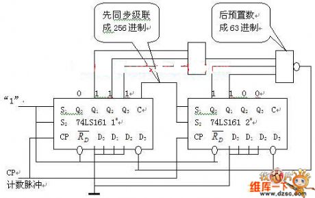
Figure:
View full Circuit Diagram | Comments | Reading(436)
ENVISION EC-1439 type display power supply circuit
Published:2011/6/5 10:00:00 Author:John | Keyword: display

ENVISION EC-1439 type display power supply circuit is shown in the following.
(View)
View full Circuit Diagram | Comments | Reading(675)
12-nary counter circuit
Published:2011/6/5 10:16:00 Author:John | Keyword: 12-nary counter
In the integrated counter with synchronous resetting performance, reset method (synchronous reset method) is used. It is different from the integrated counter with asynchronous reset function. The reset method used is called asynchronous reset method. This is determined by the difference on the actions of a synchronous reset and asynchronous reset function. According to synchronous reset function, when the reset terminal is active and is not able to immediately reset, the CP valid edge must be triggered for reset. Therefore, N-nary counter composed of the integrated counter with synchronous reset function does not have the transition state.
(View)
View full Circuit Diagram | Comments | Reading(410)
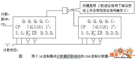
256-nary counter circuit
Published:2011/6/5 10:39:00 Author:John | Keyword: 256-nary counter
In the 160-counter, when S1 = S2 = 0, the counter to keep Q, C = 0. When S1 = S2 = 1, the counter starts to count.
A.Define 1# a low chip and define #2 a high chip.
Use a low chip’s injection output end C as the control signal, which is carried to a high chip (C edge is used to control S1 and S2 ends of high chip rather than to trigger the CP pulse end of a high counter. The value of high counter can be controlled or kept. When the low counter counts from state 0 to 8, the C is equal to zero. The counting value of high counter S1 = S2 = 0 is got. And high counter has not been compared.
(View)
View full Circuit Diagram | Comments | Reading(421)
S13033C--the 3.3 5-pole voltage steady integrated circuit
Published:2011/6/9 2:47:00 Author:qqtang | Keyword: voltage, integrated circuit

S13033C is the 3.3 5-pole voltage steady integrated circuit produced by Microsoft, which is widely used in the voltage steady circuits of video players, TV sets, computer screens, all kinds of stereo systems and small appliances,etc. 1.function features S13033C contains 3.3v voltage steady power supply circuit, voltage steady power supply ON/OFF control circuit, auto detection circuit and other additional function circuits, etc. 2.pin functions and data S13033C is in 5-pin single line package, whose pin functions and data are listed in the table.Pin functions and data of S13033C
(View)
View full Circuit Diagram | Comments | Reading(711)
photosensitive II of SCR variable frequency synchronous starter circuit
Published:2011/6/7 0:16:00 Author:John | Keyword: variable frequency synchronous starter

2CUD is used for photoelectric control. When it is affected by illumination, the photocurrent occurs to conduct 3DG8C. 3V voltage drop is generated on resistor with resistance of 2KΩ. Therefore, the next individual DG8C is also conducted (saturated). Both ends of 0.01μF capacitor is regarded as short-circuit. And double base tube BT33C stops oscillation and there is no output of line terminal.
Where there is no light, the two 3DG8C close. The double-base diode oscillator works, resulting in sharp pulse output waveform. Such would be amplified by 3DK4C to output trigger pulse waveform of the terminal, just as shown in the figure. Partial electrical angle with a pulse output is 140 ° and partial electrical angle with no pulse output is 220 °. This trigger pulse waveform is sent to the SCR inverter.
(View)
View full Circuit Diagram | Comments | Reading(538)
Field-effect transistor RSS075P03、RSS090P03 internal circuit
Published:2011/6/5 10:43:00 Author:John | Keyword: Field-effect transistor
Field-effect transistor RSS075P03、RSS090P03 internal circuit is shown below.
(View)
View full Circuit Diagram | Comments | Reading(768)
CZX-14-type display power supply circuit
Published:2011/6/9 4:57:00 Author:John | Keyword: display

CZX-14-type display power supply circuit is shown below.
(View)
View full Circuit Diagram | Comments | Reading(476)
QS6U22、QS6U24 internal circuit
Published:2011/6/9 4:57:00 Author:John

QS6U22、QS6U24 internal circuit is shown below.
(View)
View full Circuit Diagram | Comments | Reading(505)
true RMS RF power measurement system composed of a monolithic true RMS power measurement system AD8362 circuit
Published:2011/6/9 4:56:00 Author:John | Keyword: true RMS RF power measurement system

True RMS RF power measurement system composed of a monolithic true RMS power measurement system AD8362 circuit is shown below.
(View)
View full Circuit Diagram | Comments | Reading(2699)
VGA multi-frequency color monitor CTX-C1435 type power supply circuit
Published:2011/6/9 4:53:00 Author:John | Keyword: multi-frequency color monitor

VGA multi-frequency color monitor CTX-C1435 type power supply circuit is shown below.
(View)
View full Circuit Diagram | Comments | Reading(663)
RF power control system composed of a monolithic true RMS power measurement system AD8362 circuit
Published:2011/6/9 4:56:00 Author:John | Keyword: RF power control system
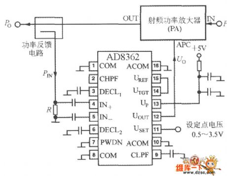
RF power control system circuit constituted by the AD8362 is just as shown in the figure. At this moment, set point voltage USET is input on pin 11 with a voltage range from 0.5V to 3.5V. Controlled system is RF power amplifier (PA). Propose the input power of PA as PI and the output power as Po. Po changes according to the with the control voltage Uo added on console termianal of APC. Utilize the power feedback circuit to form a control loop, so that the output power of PA is equal to the setting. PIN is the feedback power and R is the feedback power’s sampling resistance.
(View)
View full Circuit Diagram | Comments | Reading(655)
RDN120N25、RDN150N20 internal circuit
Published:2011/6/9 4:43:00 Author:John

RDN120N25、RDN150N20 internal circuit is shown below.
(View)
View full Circuit Diagram | Comments | Reading(657)
| Pages:1808/2234 At 2018011802180318041805180618071808180918101811181218131814181518161817181818191820Under 20 |
Circuit Categories
power supply circuit
Amplifier Circuit
Basic Circuit
LED and Light Circuit
Sensor Circuit
Signal Processing
Electrical Equipment Circuit
Control Circuit
Remote Control Circuit
A/D-D/A Converter Circuit
Audio Circuit
Measuring and Test Circuit
Communication Circuit
Computer-Related Circuit
555 Circuit
Automotive Circuit
Repairing Circuit