
Circuit Diagram
Index 1804
SVGA color display DELL VI-1428 power supply circuit
Published:2011/6/4 7:45:00 Author:John | Keyword: color display

SVGA color display DELL VI-1428 power supply circuit is shown below.
(View)
View full Circuit Diagram | Comments | Reading(2793)
Field-effect transistor US6J2 internal circuit
Published:2011/6/4 7:49:00 Author:John | Keyword: Field-effect transistor
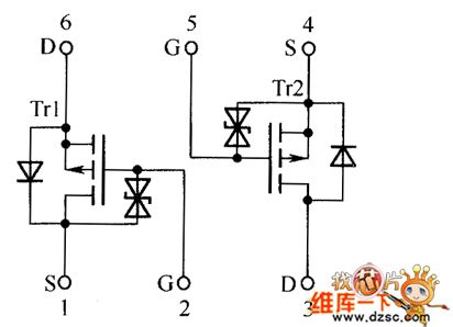
Field-effect transistor US6J2 internal circuit is shown below.
(View)
View full Circuit Diagram | Comments | Reading(633)
PARCO LFVDX-1448 type display power supply circuit
Published:2011/6/4 7:57:00 Author:John | Keyword: display

PARCO LFVDX-1448 type display power supply circuit is shown below.
(View)
View full Circuit Diagram | Comments | Reading(543)
SAA4977--the D/A converter and control integrated circuit
Published:2011/6/8 2:15:00 Author:qqtang | Keyword: D/A converter, integrated circuit


SAA4977 is a D/A converter and control integrated circuit, which is widely used in local and imported scanning large screens TV and computer screens.1.function featuresSAA4977 includes the D/A signal convert control circuit, microcomputer process circuit, storage circuit, frequency doubler signal process circuit, Y, U and V digital signal process circuit, analog Y, U and V signal process circuit and other additional circuit. The internal circuit is shown in the figure.
(View)
View full Circuit Diagram | Comments | Reading(560)
Coupled with photoelectric isolation AC load control circuit
Published:2011/6/4 8:33:00 Author:John | Keyword: AC

Microprocessor’s decoder output feedback to trigger 7476JK. And the trigger JK goes to trigger triac through the optocoupler. Therefore, the on / off control of a lamp or other AC load can be achieved. The optocoupler formed by an LED and a CdS photocell is placed within the hood. When the light emitted by LED shines on the photocell, the photocell's resistance decreases. So it will have a control voltage with proper size and direction to trigger the control pole of SCR. The SCR is conducted.
(View)
View full Circuit Diagram | Comments | Reading(550)
SAA4955TJ--The frame storage integrated circuit
Published:2011/6/8 2:28:00 Author:qqtang | Keyword: frame storage, integrated circuit


SAA4955TJ is the frame storage integrated circuit produced by Philips, which is widely used in local and imported scanning large screens TV and computer screens.1.function featuresSAA4955TJ contains the data and clock circuit, data storage and other additional circuit, whose internal circuit is shown in the figure.
The internal circuit of SAA4955TJ2.pin functions and dataSAA4955TJ is in 40-pin dual line package, whose pin functions and data are listed in the table.Pin functions and data of SAA4955TJ
(View)
View full Circuit Diagram | Comments | Reading(482)
ASIC MM5369 circuit
Published:2011/6/4 9:07:00 Author:John | Keyword: ASIC
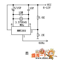
60Hz pulse circuit is formed by a 60Hz pulse generator ASIC MM5369 (pin 8 with DIP package) and the crystal with resonant frequency of 3.579545. It is used to provide support with the digital clock with frequency of 60Hz.
Oscillator signal is frequency processed through inner parts of MM5369. Such signal outputs from pin 1 with a rather stable frequency. The circuit is powered by 6 ~ 12V voltage. When the supply voltage is less than 6V, the operational reliability would be worse. Under special circumstances, the resistance of R3 in the circuit can be adjusted at about 100 ohms. Therefore, the normal operating voltage of the circuit is reduced to 4.5V.
(View)
View full Circuit Diagram | Comments | Reading(1873)
SAA3010--the integrated circuit of single chip operation controllers
Published:2011/6/8 2:39:00 Author:qqtang | Keyword: integrated circuit, single chip, operation controllers


SAA3010 is an integrated circuit of single chip operation controllers produced by Philips, which is widely used in all kinds of remote control systems, such as disc players, TV sets, stereo equipment, etc.1. Function featuresSAA3010 includes the remote order encoder, key scanning pulse generator, clock oscillating circuit, signal pre-amplifier circuit, test circuit and other additional circuit.2.pin functions and dataSAA3010 is in 28-pin dual in-line package, whose pin functions are listed as follows.
Working parameters of SAA3010
(View)
View full Circuit Diagram | Comments | Reading(2591)
32768Hz crystal oscillator circuit
Published:2011/6/4 9:35:00 Author:John | Keyword: crystal oscillator
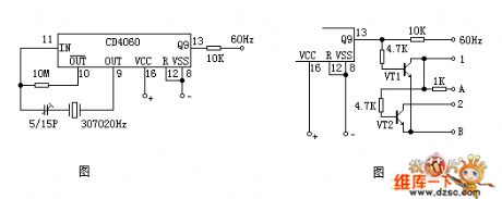
It consists of an integrated circuit CD4060, a crystal with resonant frequency of 30720Hz and other components. CD4060 is a 14-bit binary serial counter, divider and oscillator.
This circuit uses an external 30720Hz crystal to form a crystal oscillator. The oscillation signal is frequency processed through the inner parts of CD4060 and is to output accurate 60Hz frequency signal at the end of Q9 (30720 ÷ 29 = 60Hz). When the circuit is equipped with the double negative digital clock, 2b circuit shown in figure 2 can be used for polarity transform. VT1 and VT2 both use NPN type transistor, such as 9013 and 8050 and so on. Terminal A in the figure is equipped with positive power supply and Terminal B is equipped with negative power supply.
(View)
View full Circuit Diagram | Comments | Reading(2528)
practical electronic switch circuit
Published:2011/6/4 9:40:00 Author:John | Keyword: electronic switch

Practical electronic switch circuit is shown below.
(View)
View full Circuit Diagram | Comments | Reading(773)
Single-tube mosquito lamp circuit
Published:2011/6/4 9:42:00 Author:John | Keyword: mosquito lamp
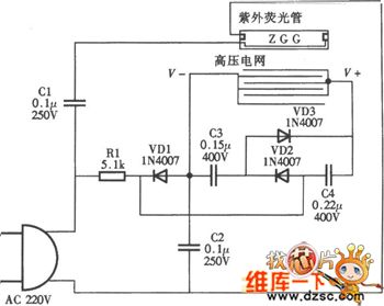
Single-tube mosquito lamp circuit is shown below.
(View)
View full Circuit Diagram | Comments | Reading(604)
binary serial counter / divider circuit
Published:2011/6/4 9:49:00 Author:John | Keyword: binary serial counter, divider
Circuit shown in figure 1 is constituted by a binary serial counter from 12 / divider and 60Hz digital time base circuit with six-inverter CD4069.
(View)
View full Circuit Diagram | Comments | Reading(1427)
Textile machine with three-stop digital control device sensitive control circuit
Published:2011/6/4 3:54:00 Author:John | Keyword: Textile machine, digital control device

While any of many root warps breaks, light barrier attached with the root warp fells down. At this time, the light barrier blocks the light source of photodiode 3DU21. The relay in the line circuit releases. And the controlled motor stops. (View)
View full Circuit Diagram | Comments | Reading(779)
SAA3007P--the integrated circuit of single chip emitters
Published:2011/6/8 2:47:00 Author:qqtang | Keyword: integrated circuit, single chip emitters


SAA3007P is an integrated circuit of single chip emitters produced by Philips, which is widely used in all kinds of remote control systems, such as disc players, TV sets, stereo equipment, etc.1. Function featuresSAA3007P includes the clock oscillating circuit, key scanning pulse generator, remote order encoder, emitting signal output circuit, user code encoder, test circuit and other additional circuits.2.pin functions and data
(View)
View full Circuit Diagram | Comments | Reading(1091)
series connection switch circuit
Published:2011/6/4 3:27:00 Author:John | Keyword: series connection switch

Light emitted by Xenon flash tube is transmitted to phototransistor MRD300 through optical fiber. Sensitive current is amplified to triggering a string of thyristors simultaneously. Therefore, high voltage of 6000V is set on loader R.
This optical trigger flip-flop can eliminate the inductance delay of general wirings. Here, the SCR devices are required to have the same rising time, aiming to prevent conduction of those slowest components from circuit triggering.
(View)
View full Circuit Diagram | Comments | Reading(1500)
SAA1280--the integrated circuit of the single chip microcomputer
Published:2011/6/8 2:59:00 Author:qqtang | Keyword: integrated circuit, single chip microcomputer


SAA1280 is an integrated circuit of the single chip microcomputer produced by Philips, which is widely used in Huari color TV sets and so on.1.function introductionSAA1280 includes CPU, clock oscillating circuit, storage control circuit, key scanning pulse generating circuit, decoding circuit of channel display voltage drive and other control and additional function circuit, etc.2.pin functions and dataSAA1280 is in 40-pin dual in-line package, whose working parameters are listed in the table.
(View)
View full Circuit Diagram | Comments | Reading(455)
TB8528--the communication RF compound integrated circuit
Published:2011/6/8 3:17:00 Author:qqtang | Keyword: communication RF, compound integrated circuit


TB8528 is a communication RF compound integrated circuit produced by Toshiba, which is widely used in all kinds of wireless phones, and it is often used with cell phone control circuit as the main machine.1.function featuresTB8528 includes the emitting/receiving signal process circuit, PLL signal process circuit, audio compressing/expanding circuit, double-conversion process circuit and so on, which is used to complete receiving modulation, PLL control, language compressing/expanding process and other functions.2.pin functions and dataTable 1. The pin functions and data of the host RF compound integrated circuit
(View)
View full Circuit Diagram | Comments | Reading(595)
TDA2030 high-fidelity active speaker circuit
Published:2011/6/4 2:27:00 Author:John | Keyword: active speaker

Chip TDA2030 is an ETC’s high fidelity amplifier integrated circuit with power 20W. It has a quite long history, but there are many manufacturers who have adopted this IC for their PC active speaker so far. This IC has been so popular. It shows that the cost-effectiveness of TDA2030 is very good TDA2030. Although within a long using history, it is not out of date.
The following circuit is a high-fidelity active speaker circuit designed with TDA2030. Dual power supply is adopted, as well as high and low tone and volume control. When designing PCB, it is suggested not trying to set the ground through the device’s pin. Therefore, the current noise can be reduced.
(View)
View full Circuit Diagram | Comments | Reading(2511)
TB1240N--the small signal process integrated circuit of color TV single chips
Published:2011/6/8 3:47:00 Author:qqtang | Keyword: process integrated, single chips
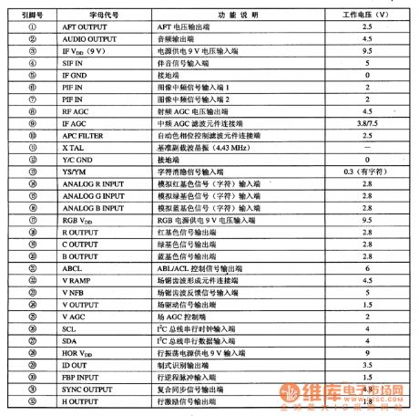
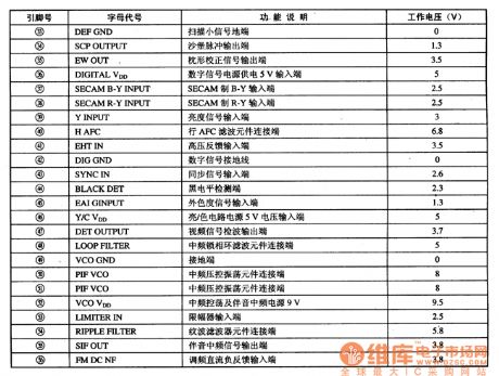
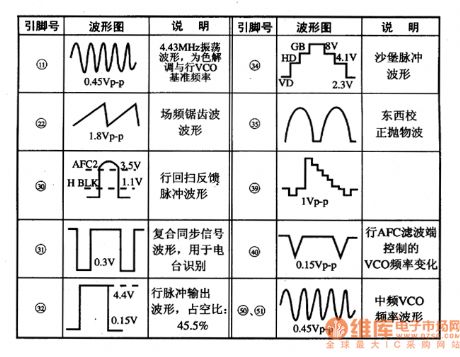
1. Function featuresTB1240N includes the image sound signal process circuit, brightness and chroma signal process circuit, travelling field scanning small signal process circuit and raster distortion adjuster, etc.2.pin functions and dataTB1240N is in 56-pin package, whose pin functions and data are listed in Table 1, and the wave forms of key pins are shown in figure 1. These are the references of judging if IC is wrong.Table 1 pin functions and data of TB1240N
Figure 1 wave forms of the key pins of TB1240N
(View)
View full Circuit Diagram | Comments | Reading(583)
TAB7O0N--The intermediate frequency channel integrated circuit
Published:2011/6/8 3:58:00 Author:qqtang | Keyword: intermediate frequency, integrated circuit


1.function featuresTAB7O0N includes the image IF amplifier circuit, AGC circuit, AFC circuit, sound IF signal process circuit, frequency discrimination circuit and other additional circuits. The internal circuit and typical application circuit are shown in Figure 1.Figure 1. The internal circuit and typical application circuit of TAB7O0N
2.pin functions and dataTAB7O0N is in 20-pin dual line package, whose pin function introductions are shown in figure 1, and the pin working parameters are listed in table 1.Table 1. Main working parameters of TAB7O0N
(View)
View full Circuit Diagram | Comments | Reading(445)
| Pages:1804/2234 At 2018011802180318041805180618071808180918101811181218131814181518161817181818191820Under 20 |
Circuit Categories
power supply circuit
Amplifier Circuit
Basic Circuit
LED and Light Circuit
Sensor Circuit
Signal Processing
Electrical Equipment Circuit
Control Circuit
Remote Control Circuit
A/D-D/A Converter Circuit
Audio Circuit
Measuring and Test Circuit
Communication Circuit
Computer-Related Circuit
555 Circuit
Automotive Circuit
Repairing Circuit