
Circuit Diagram
Index 1809
EGA monitor CTX-C146 type power supply circuit
Published:2011/6/9 4:42:00 Author:John | Keyword: EGA monitor

EGA monitor CTX-C146 type power supply circuit is shown below.
(View)
View full Circuit Diagram | Comments | Reading(676)
VGA color monitor CTX-C15-type power supply circuit
Published:2011/6/9 4:42:00 Author:John | Keyword: VGA color monitor

VGA color monitor CTX-C15-type power supply circuit is shown below.
(View)
View full Circuit Diagram | Comments | Reading(737)
Color display DATAS HC-7423 type power supply circuit
Published:2011/6/9 4:40:00 Author:John | Keyword: Color display

Color display DATAS HC-7423 type power supply circuit is shown below.
(View)
View full Circuit Diagram | Comments | Reading(674)
in-phase adder circuit
Published:2011/6/9 4:39:00 Author:John | Keyword: in-phase adder

in-phase adder circuit
(View)
View full Circuit Diagram | Comments | Reading(858)
TA7230--the dual channel audio power amplifier integrated circuit
Published:2011/6/8 21:45:00 Author:qqtang | Keyword: audio power amplifier, integrated circuit


TA7230 is the dual channel audio power amplifier integrated circuit produced by Toshiba, which is widely used in stereo systems, such as car stereos, domestic stereos and so on.1.function features TA7230 contains 2 lines of same-function audio power amplifier circuits, wave filtering circuit, and the silence/mute circuit of power supply protection, whose pin functions are shown in Figure 1. Figure1. The internal circuit of TA7230
2. Pin functions and data TA7230 is in 10-pin in-line package, whose pin functions and data are listed in table1.
(View)
View full Circuit Diagram | Comments | Reading(3442)
SA7280P/M2--the NICAM decoding integrated circuit
Published:2011/6/8 21:35:00 Author:qqtang | Keyword: NICAM, integrated circuit


SA7280P/M2 is the NICAM decoding integrated circuit produced by Philips, which is often used in large screen color TV.SA7280P/M2 is in 28-pin dual line package, whose internal circuit is shown in the figure, and its pin functions and data are listed in the table, for reference.
The internal circuit of SA7280P/M2The pin functions and data of SA7280P/M2 (View)
View full Circuit Diagram | Comments | Reading(733)
SA97018--the communication single chip microcomputer integrated circuit
Published:2011/6/8 21:27:00 Author:qqtang | Keyword: communication single chip, microcomputer


SA97018 is a communication single chip microcomputer integrated circuit, which is often used in COSUN phones, such as HA8188(10)P/TDL-LCD and so on.1.function featuresSA97018 contains the key pulse generating circuit, key order encoding circuit, clock oscillator circuit, digital volume adjusting circuit, silence/mute control circuit, ring control circuit and other kinds of control circuit, etc.2.pin functionsSA97018 is in 42-pin square package, whose pin functions are listed in the table.Pin functions of SA97018
(View)
View full Circuit Diagram | Comments | Reading(720)
OP249--the dual computing amplifier integrated circuit
Published:2011/6/9 7:45:00 Author:qqtang | Keyword: computing amplifier, integrated circuit

OP249 is a dual computing amplifier integrated circuit, which belongs to general type IC, it is widely used in all kinds of electric apparatus, such as the stereo equipment, computer system, medical device, instruments and household appliance, etc.1.the internal circuit and featuresOP249 contains two same-function computeing amplifiers, which can form the noninverting and inverting amplifier of different terms, it can also be used as the voltage comparator. Its internal circuit is in the figure.
The internal circuit of OP249 (View)
View full Circuit Diagram | Comments | Reading(757)
The P83C266BDR integrated circuit
Published:2011/6/9 7:33:00 Author:qqtang | Keyword: integrated circuit


P83C266BDR is a single chip microcomputer integrated circuit produced by Philips, which is used in both local and imported large screen color TV.1. Function featuresP83C266BDR consists of the CPU, clock oscillating circuit, reset control circuit, key order decoding circuit, I2C general control circuit, infrared remote order signal process circuit, screen displayed letter generating and process circuit, standby/starting up control circuit and other control and additional function circuits.2.pin functions and data
(View)
View full Circuit Diagram | Comments | Reading(689)
ONWA KWEC44.1--the single chip microcomputer integrated circuit
Published:2011/6/8 22:05:00 Author:qqtang | Keyword: single chip, microcomputer


1.function featuresONWA KWEC44.1 consists of the CPU, system reset control circuit, clock oscillator circuit, key pulse generateing circuit, key order signal decoding circuit, screen symbol signal generating and processing circuit,TV/AV control circuit, system shifting control circuit, stand by/start up convert control circuit and other control and additional function circuit, etc.2.pin functions and dataONWA KWEC44.1 is in 52-pin dual line package, whose pin symbols and data are listed in the table.
(View)
View full Circuit Diagram | Comments | Reading(1738)
NT6827--the letter generating integrated circuit
Published:2011/6/9 7:56:00 Author:qqtang | Keyword: letter generating, integrated circuit

NT6827 is a letter generating integrated circuit, which is widely in the screens of all makes of color TV, such as Samsung and TCL color screens.1.function featuresNT6827 consists of the reference voltage circuit, blank signal process circuit, I2C general connector circuit, letter display signal generating circuit and other additional function circuits, etc.2.pin functions and dataNT6827 is in 16-pin dual in-line package, whose pin functions and data are listed in the table.
(View)
View full Circuit Diagram | Comments | Reading(759)
NJM4558S--the dual computing amplifier circuit
Published:2011/6/9 8:16:00 Author:qqtang | Keyword: computing amplifier


NJM4558S is a dual computing amplifier integrated circuit produced by JRC Corp., Japan, which is widely used in all kinds of areas, such as CD players, VCD players, DVD players, stereo equipment, electric auto control equipment, instruments, meters, all kinds of household appliances, computers and their screens, car power appliances and car stereos, cooling electric appliances, office electric appliances, etc.NJM4558S is in 8-pin dual line package, whose internal circuit is shown in the figure, and its pin functions and data are listed in the table.
(View)
View full Circuit Diagram | Comments | Reading(1724)
NJM2100--the audio signal amplifier integrated circuit
Published:2011/6/9 8:07:00 Author:qqtang | Keyword: audio signal, integrated circuit


NJM2100 is an audio signal amplifier integrated circuit produced by JRC Corp., Japan, which is widely used in all kinds of stereo karaoke systems, such as VP3000 disc player, etc.1.pin functions and dataNJM2100 contains two lines of same-function audio signal amplifier circuits, and it is in 8-pin in-line package, its pin functions and data are listed in the table.The pin functions and data of NJM2100
The typical application circuit of NJM2100 (View)
View full Circuit Diagram | Comments | Reading(2320)
The starting and power supply circuit of Santana(chassis No. 3ZMP003182)
Published:2011/5/14 23:32:00 Author:Borg | Keyword: power supply, Santana

1-battery; 2-starter; 3-starting interlocking switch; 4-gear position indicator(with auto transmission); 5-fuel tank electrical pump; 5a-cold starting temperature control switch; 6-integrate alternator; 7-radio filter capacitor; 8-charging indicator; 9-power supply system relay; 10-oil assistance pump; 11-oil pump; 12-igniting switch; 13-jet resistance; 14-Ⅰjar jet; 15-jet resistance; 16-IV jar jet; 17-jet resistance; 18-Ⅱjar jet; 19-jet resistance; 20-Ⅲ jar jet (View)
View full Circuit Diagram | Comments | Reading(1171)
The connector and wiring circuit on the ground of Santana central connection box
Published:2011/5/14 23:56:00 Author:Borg | Keyword: connector, wiring circuit, Santana, connection box
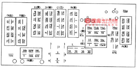
The ground of the central connection box is the juncture of the wires throughout the whole car, of which 6 bundles are from instrument plate and front wall, 2 from car head, 1 from right-head, 1 from rear, and there are also some dual-point and single-point connectors whose position are as shown in Figure 1. It's useful to know the connector positions and wire codes for reading the following pictures.
There are two kinds of line codes as follows:
Letters are used to represent the strap connections. (View)
View full Circuit Diagram | Comments | Reading(364)
The wires off/on detection circuit of Santana 2000GLi
Published:2011/5/16 19:50:00 Author:Borg | Keyword: detection circuit, Santana

When we engage in the detection job, we should connect the box V .A Gl598 and cables V .A .G1598-9 to the connector of the wire bundles, but let the computer of line.
(1)shut down the igniting switches and pull off the connector of the engine control computer, then connect the box V .A Gl598 and cables V .A .G1598-9 to the control wires of the engine computer, by which we detect whether the circuit is off or short (computer is not connected).(2)Shut down the igniting switch and connect the box V .A Gl598 and cables V .A .G1598-9 to the engine control computer, by which we detect the voltage between the sensor and each terminal of the computer. (View)
View full Circuit Diagram | Comments | Reading(586)
Electronic rodent repeller circuit diagram 5
Published:2011/6/7 4:40:00 Author:Lucas | Keyword: Electronic rodent repeller

The electronic rodent repeller circuit is composed of the trigger control circuit, sound and light alarm circuit, wireless transmitter circuit and high-voltage generator output circuit, and the circuit is shown as the chart. Control circuit is composed of trigger sensor (the two electrodes between A and B ), transistors V1 ~ V4, resistors R1, R2, capacitors C2, C3, diode VD1 and relay K. Sound and light alarm circuit is composed of the music integrated circuit IC, transistor V5, speaker BL, resistor R5 and LEDs VL1, V12. Wireless transmitter circuit consists of resistors R3, R4, capacitors C4 ~ C8, inductor L, transistor V6 and antenna W. High-voltage generator output circuit consists of the resistor R6, capacitors C9, C1O, step-up transformer T, the transistor V7, diode VD2 and high-voltage electrodes.
(View)
View full Circuit Diagram | Comments | Reading(919)
Electronic rodent repeller circuit diagram 6
Published:2011/6/7 4:40:00 Author:Lucas | Keyword: Electronic rodent repeller

The electronic rodent repeller circuit is composed of the power circuit, infrared control circuit and high-voltage circuit, and the circuit is shown as the chart. Power circuit is composed of the power transformer T, bridge rectifier UR, filter capacitors C4, C5, and three-terminal voltage regulator integrated circuit IC2. Infrared control circuit consists of infrared light-emitting diode VL1, infrared photodiode VD1, transistor V, resistors R1 ~ R6, capacitors C1 ~ C3, integrated circuit IC1, light-emitting diode VL2 and solid-state relay KN. High voltage circuit is composed of the solid-state relay KN, resistor, capacitors C6, C7, diodes VD2, VD3, and high-voltage electrodes. 220V AC voltage is bucked by T, rectified by UR, filtered by C5 and stabilized by IC2 to provide +6 V voltage for infrared control circuit.
(View)
View full Circuit Diagram | Comments | Reading(954)
Loom controller circuit diagram
Published:2011/5/30 6:33:00 Author:Lucas | Keyword: Loom controller

The loom controller circuit consists of touching control circuit, light control circuit, overheat protection circuit, working status indicator circuit and control implementation circuit, the circuit is shown as the chart. Touching control circuit is composed of touching electrode A and the pin 2 of time-base integrated circuit IC2. Light control circuit consists of infrared emitting diode VL1, infrared phototransistor V5, transistor V6, resistors R10 and R3 ~ R6 and the pin 7 of IC. Thermal protection circuit consists of transistors V1 ~ V4, diode VD1, resistors R1 and R2, capacitors C1 and C2, potentiometer RP and pin 6 of the internal IC. Control implementation circuit is composed of the transistor V7, relay K, resistor R9 and diode VD2. Working status indicator circuit consists of resistors R7, R8 and LEDs VL1, VL2.
(View)
View full Circuit Diagram | Comments | Reading(679)
Metal proximity switch circuit diagram
Published:2011/5/29 2:19:00 Author:Lucas | Keyword: Metal proximity switch
Metal proximity switch circuit consists of the high-frequency oscillator circuit, voltage rectifier circuit, and electronic switching circuit, the circuit is shown as the chart. High-frequency oscillator circuit consists of high-frequency transformer T, potentiometer RP1, resistors R1 ~ R3, capacitors C1 ~ C3 and transistor V1. Doubler rectifier circuit is composed of the diodes VD1 and VD2, capacitor C4 and resistor R4. Electronic switching circuit consists of transistors V2 and V3, potentiometer RP2, optocoupler VLC and resistors R5, R6. R1 ~ R6 use 1/4W metal film resistors or carbon film resistors. RP1 selects organic, solid potentiometer or variable resistor; RP2 uses synthetic carbon potentiometer or variable resistor. C1, C2 and C4 select monolithic capacitors; C3 uses high-frequency ceramic capacitor. VD1 and VD2 use IN4148 silicon switching diode. V1 and V2 use 59013 or 3DG6 silicon NPN transistor; V3 uses 58050 silicon NPN transistor. VLC uses 4N25 or 4N26 optocoupler.
(View)
View full Circuit Diagram | Comments | Reading(1697)
| Pages:1809/2234 At 2018011802180318041805180618071808180918101811181218131814181518161817181818191820Under 20 |
Circuit Categories
power supply circuit
Amplifier Circuit
Basic Circuit
LED and Light Circuit
Sensor Circuit
Signal Processing
Electrical Equipment Circuit
Control Circuit
Remote Control Circuit
A/D-D/A Converter Circuit
Audio Circuit
Measuring and Test Circuit
Communication Circuit
Computer-Related Circuit
555 Circuit
Automotive Circuit
Repairing Circuit