
Circuit Diagram
Index 1815
the circuit of auto water supplier for agriculture(1)
Published:2011/6/4 20:41:00 Author:Ariel Wang | Keyword: auto, water, supplier, agriculture
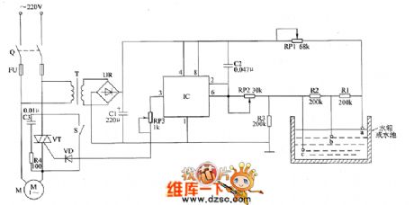
When the knife switch Q gets through,AC 220V voltage is reduced by T,commuted by UR and filtered by C1.It provides 10V DC voltage(Vcc) for input circuit and control circuit of water level detection.When the water level of the water tank reaches electrode b,the resistence of water will be short-circuit by R2.It makes the voltage of IC's 2nd-pin and 6th-pin higher than Vcc/3,but lower than 2Vcc/3(about Vcc/2).The inner circuit sets up.The 3rd-pin still output high level.VT stays conducted.Electric motor of water pump M goes on pumping.When the water level of the water tank reaches electrode a,the resistence of water will be short-circuit by R1.It makes the voltage of IC's 2nd-pin and 6th-pin higher than 2Vcc/3.It makes the high level of 3rd-pin jump to low level.VT stops. M is power-off .And it stops pumping.
(View)
View full Circuit Diagram | Comments | Reading(495)
the circuit of electrifying intermittent controller part 4
Published:2011/6/5 9:25:00 Author:Ariel Wang | Keyword: electrifying, intermittent, controller
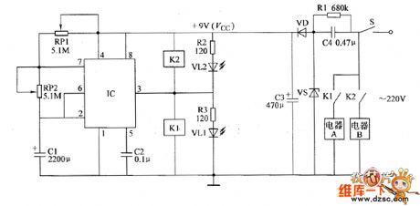
At the moment of the mains power supply gets through,the voltage of C1 can't be changed suddenly.IC's 2nd-pin is low level(lower than Vcc/3),3rd-pin outputs high level.It conducts K1 to pull in. Its open point is switch in.The electric appliance A is conducted to work.At the same time VLI is lighted.After that,+9V voltage charges C1 by RP1 and RP2.It makes the voltage of C1 goes up and up.When the voltage is beyond 2Vcc/3.The in-circuit turns over.The 3rd-pin turns high level to low level.K1 releases.K2 pulls in.Electric appliance A stops working.Electric appliance B is conducted to work.At the same time,VL1 dies out.VL2 is lighted.
(View)
View full Circuit Diagram | Comments | Reading(456)
the circuit of electrifying intermittent controller part 3
Published:2011/6/6 2:02:00 Author:Ariel Wang | Keyword: electrifying , intermittent, controller
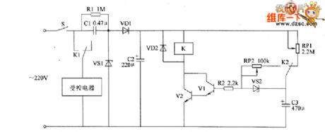
When the mains switch S gets through,AC 220V voltage is reducted by C1.It is regulated by VS1.It is commutated by VD1.And it is filtered by C2.Then it generates about 15V DC working voltage.It provides voltage for relay K .It charges CS by RP1.When the voltage of C3 reaches a certain value.VS2 conducts. V1 and V2 is saturated to conduct. The normally closed contact is disconnected.The controlled appliances(for example ,low power electric heater,electric motor of water pump,oxygen enrichment equipment,scavenger fan and humidifier ect) are conducted to work.C3 discharges base electrode of V1 by RP2 and R2.So V1 and V2 stay conducted.The controlled appliances go on to work. (View)
View full Circuit Diagram | Comments | Reading(460)
the circuit of humidity detector for food part 2
Published:2011/6/6 1:24:00 Author:Ariel Wang | Keyword: humidity, detector, food
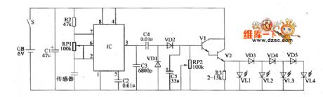
When to be detected,the graininess foodstuffs are put into the two plate electrodes of the capacitive humidity sensor .The air medium between two plate electrodes turns to dissipation change.It changes the capacitance.The oscillation frequency of multivibrator changes at the same time.The more humidity amount of foodstuffs ,the smaller amount of the sensor.And oscillation frequency of the multivibrator will become faster.The DC voltage of V1 base electrode becomes higher.The output voltage of V2 emitter becomes higher.LED(VL1-VL4) will give more light.
(View)
View full Circuit Diagram | Comments | Reading(420)
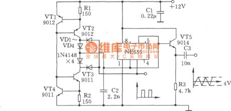
Triangular Wave and Square-wave Generator Circuit Composed of NE555
Published:2011/6/4 10:08:00 Author:Joyce | Keyword: Triangular Wave , Square-wave , Generator, NE555
(View)
View full Circuit Diagram | Comments | Reading(671)
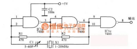
NAND TTL Crystal Oscillator Circuit
Published:2011/5/29 1:38:00 Author:Joyce | Keyword: NAND , TTL , Crystal Oscillator
View full Circuit Diagram | Comments | Reading(1630)
12kHz Intermediate-frequency Oscillator Circuit
Published:2011/6/2 3:49:00 Author:Joyce | Keyword: 12kHz, Intermediate-frequency , Oscillator
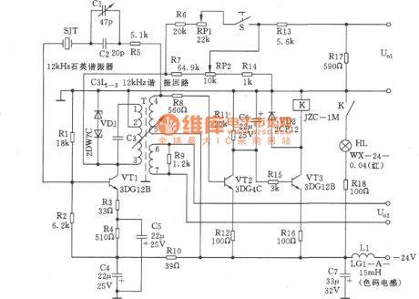
The 12kHz intermediate frequency oscillators in the graph is composed of 12kHz quartz oscillators, output level adjustment,a level ascending circuit and a alarm circuit. It uses a new single tube tuning transformer feedback oscillator circuit. In the feedback circuit, 12 kHz quartz crystal resonators are connected in series, thus the oscillation frequency depends on the performance of the l2kHz quartz crystal resonators .With regard to improving the reliability of oscillators and stability of the output, it uses AC circuit with fixed amplitude. In other respects, this circuit makes use of components with stable performance, and tries to simplify the circuit, thus ensuring good performance. (View)
View full Circuit Diagram | Comments | Reading(786)
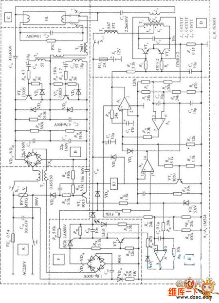
AM A-4040-type display power supply circuit
Published:2011/6/4 7:47:00 Author:John | Keyword: display

AM A-4040-type display power supply circuit is shown below.
(View)
View full Circuit Diagram | Comments | Reading(696)
LM1875 current feedback BTL circuit
Published:2011/6/3 20:12:00 Author:chopper | Keyword: current feedback, BTL

View full Circuit Diagram | Comments | Reading(3168)
Dodge vacuum tube circuit
Published:2011/6/3 9:42:00 Author:chopper | Keyword: Dodge, vacuum tube

View full Circuit Diagram | Comments | Reading(564)
automobile battery charger circuit
Published:2011/6/3 20:10:00 Author:chopper | Keyword: automobile, battery charger

There is a automobile battery charger of adjustable type.The charging voltage between 6V and 50V is adjustable,and the maximum charge current can reach 20A.It applies to automobile battery charger of different type,such as 12V,24V,36V and so on.
(View)
View full Circuit Diagram | Comments | Reading(5318)
Automatic charger circuit
Published:2011/6/3 20:04:00 Author:chopper | Keyword: Automatic charger

View full Circuit Diagram | Comments | Reading(992)
power supply of energy-saving fluorescent light in emergency circuit
Published:2011/6/3 9:40:00 Author:chopper | Keyword: fluorescent ligh, energy-saving, in emergency, power supply
View full Circuit Diagram | Comments | Reading(647)
high voltage supply of neon light circuit
Published:2011/6/3 19:57:00 Author:chopper | Keyword: high voltage supply, neon light
View full Circuit Diagram | Comments | Reading(744)
300kHz Signal Generator Circuit
Published:2011/6/4 9:39:00 Author:Joyce | Keyword: 300kHz , Signal Generator
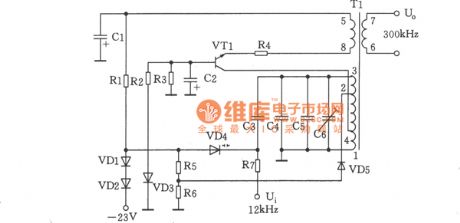
As shown in the figure is a 300 kHz signal generator. The voltage-controlled oscillator consists of VT1,T1, VD4 and other relevant components, with LC collector tuning.VT1 is the oscillating tube, while variode VD4, capacitance C3 ~ C6 and inductance of transformer T1`s windings 1 ~ 3 compose a tuned circuit. The variode VD4 works as control voltage is sent to its negative terminal to change its electric capacity. Oscillating signal is output by windings 6 ~ 7 of T1. Among them, C6 is a frequency trim capacitance. VD3 is to stabilize the working voltage of oscillator stage, and the stabilized voltage is 6.8 V ± 0.2 V. (View)
View full Circuit Diagram | Comments | Reading(720)
Dodge after heater and air conditioning system circuit
Published:2011/6/6 9:57:00 Author:chopper | Keyword: Dodge, after heater, air conditioning system

View full Circuit Diagram | Comments | Reading(632)
basic feedback magnifying circuit
Published:2011/6/6 9:55:00 Author:chopper | Keyword: feedback, magnifying

View full Circuit Diagram | Comments | Reading(414)
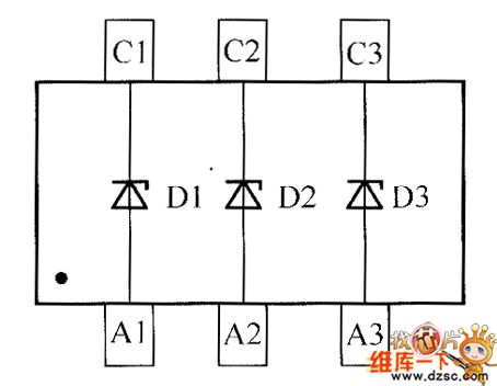
crystal diode DDZX9716TS internal circuit
Published:2011/6/6 9:54:00 Author:chopper | Keyword: crystal diode, internal
View full Circuit Diagram | Comments | Reading(342)
AP3012 positive-negative power supply circuit
Published:2011/6/6 9:54:00 Author:chopper | Keyword: positive-negative power supply

View full Circuit Diagram | Comments | Reading(1068)
The week digit displayer circuit
Published:2011/6/7 22:28:00 Author:qqtang | Keyword: digit displayer

The week digit display circuitThe circuit of the week digit display circuit is in the figure, of which IC1 is a decimal counter/distributor, IC2 is a special integrated circuit CH233 of TV channels, and it can drive LED digital displayers directly and make it display the numbers of 1-8. The clock control signals in the circuit is from the PM terminal of large crystal clock, it is outputting a converting pulse at o'clock every night. When the pulse signal is amplified by VT1, it is delivered to the CP terminal of IC1, by every input pulse, the high LEV of IC1 Qo-Q7 output terminal moves in turn.
(View)
View full Circuit Diagram | Comments | Reading(504)
| Pages:1815/2234 At 2018011802180318041805180618071808180918101811181218131814181518161817181818191820Under 20 |
Circuit Categories
power supply circuit
Amplifier Circuit
Basic Circuit
LED and Light Circuit
Sensor Circuit
Signal Processing
Electrical Equipment Circuit
Control Circuit
Remote Control Circuit
A/D-D/A Converter Circuit
Audio Circuit
Measuring and Test Circuit
Communication Circuit
Computer-Related Circuit
555 Circuit
Automotive Circuit
Repairing Circuit