
Circuit Diagram
Index 1818
CGA NEC JB-1410P2B type monochrome display power supply circuit
Published:2011/6/5 4:18:00 Author:John | Keyword: monochrome display

CGA NEC JB-1410P2B type monochrome display power supply circuit is shown below.
(View)
View full Circuit Diagram | Comments | Reading(603)
Field-effect transistor RTF010P02、RTF011P02、RTF015P02 internal circuit
Published:2011/6/5 4:16:00 Author:John | Keyword: Field-effect transistor

Field-effect transistor RTF010P02、RTF011P02、RTF015P02 internal circuit is shown below.
(View)
View full Circuit Diagram | Comments | Reading(654)
color display SAMPO KOS-1429 type power supply circuit
Published:2011/6/5 4:15:00 Author:John | Keyword: color display

Color display SAMPO KOS-1429 type power supply circuit is shown below.
(View)
View full Circuit Diagram | Comments | Reading(617)
555 calculator/stopwatch convertor circuit
Published:2011/6/7 2:11:00 Author:TaoXi | Keyword: 555, calculator, stopwatch, convertor
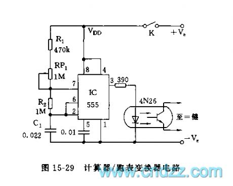
As the figure 15-29 shows, the convertor is composed of the time-base pulse generator and the photoelectric isolating device. The astable multivibrator is composed of the 555 and the R1, R2, RP1, C1, the oscillation frequency f=1.44/(R1+RP1+2R2)C1, by adjusting RP1, you can make the frequency to 60Hz. The output of pin-3 adds to the photoelectric coupler through the current limiting resistor, and the output also adds to any calculator buttons which have the automatic constant, so it can be used as the stopwatch.
(View)
View full Circuit Diagram | Comments | Reading(1373)
The powersaver circuit of 555 fridge
Published:2011/5/27 0:48:00 Author:Borg | Keyword: powersaver circuit

Customers often pay attention to the reduced power consumption of the fridge while its functions are not effected. The circuit shown in Figure 13-3 is applied in all types of two-door fridges, under the condition of not changing its internal control circuits, it can cut off the defrost heating wire in the fridge and save the power.The circuit consists of step-down rectifier circuit, test switch and oscillating control circuit,etc. 555,R2,R4 and C3 form the controllable oscillator, and the oscillator is under the control of the switch tube VT1. When VT1 is conducting, the 4-pin of 555 is in a low LEV and it stops oscillating.
(View)
View full Circuit Diagram | Comments | Reading(1714)
The over voltage, low voltage and off-delay operation protection circuit of 555 fridge
Published:2011/5/27 1:11:00 Author:Borg | Keyword: over voltage, low voltage, off-delay operation, protection circuit
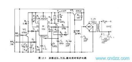
See as Figure 13-9, this is a over voltage and low voltage sampling circuit consisting of RP1,VT1 and RP2,C2MD2, etc, 1/2 of which is the over or low voltage trigger circuit; and the other 1/2 is the time delay circuit, the delaying time is td=1.1R7C4, which is about 6min. The output is controlled by the relay control circuit, the the off-delay operation is over, the 9-lead outputs a low LEV, and J pulls in, J2-2 and J1-1 closes, and the outlet CZ gets power, then the fridge is working.
Figure 13-9 The over voltage, low voltage and off-delay operation protection circuit ofthe fridge (View)
View full Circuit Diagram | Comments | Reading(1977)
The simple washing machine timer circuit of 555 fridge
Published:2011/5/27 1:23:00 Author:Borg | Keyword: washing machine, timer circuit

See as Figure 13-19, the washing machine timer is a single steady timing circuit, which is under the control of the state of water level switch. The single steady time isTd=1.1[(R1~R5)+2R6]CThe time can be changed by the programmed timing switch.
Figure 13-19 The simple washing machine timer circuit ofthe fridge (View)
View full Circuit Diagram | Comments | Reading(2235)
The protector circuit of the 555 multiple functional fridge
Published:2011/5/27 19:36:00 Author:Borg | Keyword: protector circuit, multiple functional fridge
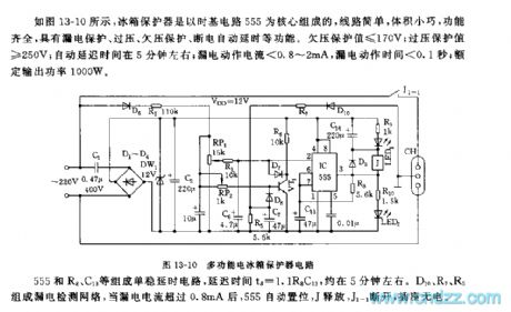
See as Figure 13-10, the fridge protector is formed on the basis of time-base circuits, whose wiring is simple, size is small and functions are complete, and the circuit has functions of leakage protection, over voltage protection, low voltage protection and power failure time delay, etc. The value of low voltage protection is ≤170V; the value of over voltage protection is ≥250V; the auto time delay is about 5min; leakage reacting current is <0.8~2mA, the reacting time is< 0.1S; and the rated output power is 1000W.
555,R8,C13 and so on forms a single steady time delay circuit, the delaying time is td=1.1R8C13, which is about 5min. (View)
View full Circuit Diagram | Comments | Reading(796)
The internal lighting lamp state test circuit of 555 fridge
Published:2011/5/27 0:11:00 Author:Borg | Keyword: internal lighting lamp, test circuit

555, R2,R3 and C1 consist a coercive multi-oscillator, the 4-lead of the coercive terminal links to the C terminal of LED 3DU5, under the light, 3DU5 is in a low resistance, so the 4-lead of 555 is in a low LEV and it is forced to be reset, the oscillator stops working and the loudspeaker is quiet; when there is no light, 3DU is blocked and its resistance is high, the 4-lead is in a high LEV, the 555 oscillator is starting to work and it frequency is f=1.44/(R2-2R3)C1The shaking frequency of the parameter in the figure is 993Hz.
Figure 13-20 The internal lighting lamp state test circuit of the fridge (View)
View full Circuit Diagram | Comments | Reading(843)
The timing ventilation circuit of 555 auto temperature control
Published:2011/5/27 20:32:00 Author:Borg | Keyword: ventilation circuit, auto temperature control
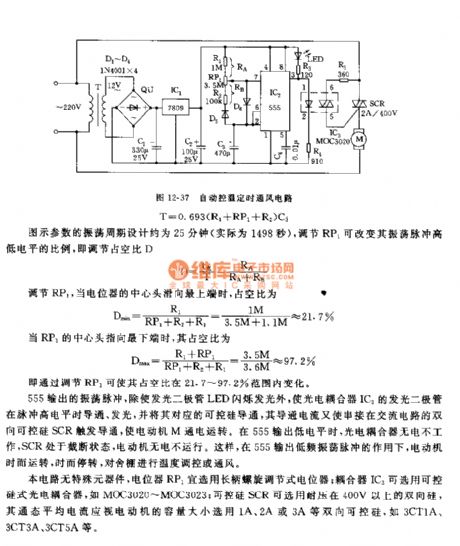
The temperature control ventilation circuit consists of step-down rectifier circuit, long period multi-resonate oscillator, photocoupler and controllable silicon control circuit, etc, which is simple and stable. The circuit can be used to ventilate and cool poultry houses, animal shelters and warm houses,etc. The circuit is as shown in Figure 12-37. The rectifier circuit consists of step-down transformer T, full bridge rectifier QU and C1, etc, the rectified voltage of about 14V is stabilized by the 3-terminal voltage stabilizer LM7809, and it reduces to be a +9V voltage as the working voltage of the backward-stage circuit.
(View)
View full Circuit Diagram | Comments | Reading(695)
the control circuit of electric fence part 3
Published:2011/6/6 9:22:00 Author:Ariel Wang | Keyword: control , electric , fence

When DC current power-supply is adopted,S1 and S2 get through.The self-exciting multivibrator works.It turns 6V DC voltage to the swing of 60V square-wave voltage by T2.The square wave voltage is commutated by UR and it is filtered by C1.It charges C3 and C2 by R3 and R4.When the voltage of C3 reaches the break over voltage of DIAC V3.V3 is conducted.C3 discharges the gate of thyristor VT by V3.It triggers VT to conduct.After VT is conducted,the electric charge stored on C2 discharges quickly by VT and T3.It generates pulse high voltage on the secondary winding of T3.
(View)
View full Circuit Diagram | Comments | Reading(1206)
the control circuit of electric fence part 4
Published:2011/6/6 1:56:00 Author:Ariel Wang | Keyword: control, electric, fence

When the mains switch S gets through,the battery GB provides the whole machine all connected circuit +6V voltage.The pulse generator will generate narrow pulse voltage signal after it is conducted to work.It is buffered to amplifier by V1 .Then it will drive V2.It makes V2 at a switch state of whether conducted or stopped.It will control the pulse current which goes into the primary winding of T.The pulsed high voltage generated by the secondary winding of T goes to the bare wire of electric fence.When the electric quantity of the storage battery is enough,VS and V3 are conducted.The 8th-pin of IC becomes low level.V4 stops.VL is not lighted.HA doesn't give a sound.
(View)
View full Circuit Diagram | Comments | Reading(1353)
the circuit of soil humidity monitor part 1
Published:2011/6/2 1:02:00 Author:Ariel Wang | Keyword: soil, humidity , monitor
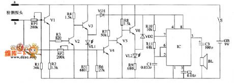
When the soil is too wet(the humidity is over the value of upper limit set by RP2),the resistance between two humidity probe electrodes reduces.It makes V1,V2 and V4 conducted of saturation.It stops V3 and V5 .It conducted V6.It lights VL2.Those indicate the humidity of the soil is too high..At the same time,VD2 is conducted.The audiofrequency oscillator works,BL will ring.
When the soil is too dry(the humidity is lower than the value of low limit set by RP1),the resistance between two humidity probe electrodes increases.It makes V3 and V5 conducted of saturation.It stops V1 ,V2,V4 and V6 .It conducted V6.It lights VL1.Those indicate the humidity of the soil is too low.At the same time,VD1 is conducted.The audiofrequency oscillator works,BL will ring.
(View)
View full Circuit Diagram | Comments | Reading(632)
The tester circuit of transistor and common cathode digital pipe
Published:2011/6/6 23:40:00 Author:qqtang | Keyword: tester circuit, transistor, common cathode

See as the figure, the positive power supply Vcc and the ground terminal GND are connected with the circuit under test by a clamp, the UIN pole is linked to the tested point by a probe.when the tested point is in a high LEV, VT1 is conducting, the h,c and g are in high LEV and glowing, and the e and f are glowing by separating pipe VD1 at the same time, the digital pipe indicates a H ; when the tested point is in a LEV, VT2 is conducting,and d,e and f are glowing, a 1 is shown. VD1 and VD2 fulfill the separating functions, and complete the functions of logic OR (which can be substituted by a second input terminal). (View)
View full Circuit Diagram | Comments | Reading(489)
The principle circuit of classical Motorola L7 cellphone (6/7)
Published:2011/6/3 7:10:00 Author:Seven | Keyword: principle circuit, Motorola

View full Circuit Diagram | Comments | Reading(436)
The fabrication circuit of 3-pipe modulation wireless microphones (2)
Published:2011/6/3 6:33:00 Author:Seven | Keyword: fabrication circuit, wireless microphones

View full Circuit Diagram | Comments | Reading(422)
The color picture of Nokia 5210 repairing (1)
Published:2011/6/3 6:36:00 Author:Seven | Keyword: color picture

View full Circuit Diagram | Comments | Reading(771)
The color picture of Nokia 5210 repairing (2)
Published:2011/6/3 6:41:00 Author:Seven | Keyword: color picture

View full Circuit Diagram | Comments | Reading(1072)
The color picture of Nokia 3650 repairing (1)
Published:2011/6/3 6:38:00 Author:Seven | Keyword: color picture

View full Circuit Diagram | Comments | Reading(669)
The color picture of Nokia 3650 repairing (2)
Published:2011/6/3 6:39:00 Author:Seven | Keyword: color picture

View full Circuit Diagram | Comments | Reading(490)
| Pages:1818/2234 At 2018011802180318041805180618071808180918101811181218131814181518161817181818191820Under 20 |
Circuit Categories
power supply circuit
Amplifier Circuit
Basic Circuit
LED and Light Circuit
Sensor Circuit
Signal Processing
Electrical Equipment Circuit
Control Circuit
Remote Control Circuit
A/D-D/A Converter Circuit
Audio Circuit
Measuring and Test Circuit
Communication Circuit
Computer-Related Circuit
555 Circuit
Automotive Circuit
Repairing Circuit