
Circuit Diagram
Index 1813
TDA3654 field scanning output integrated circuit
Published:2011/6/8 19:02:00 Author:Christina | Keyword: field scanning, output, integrated circuit
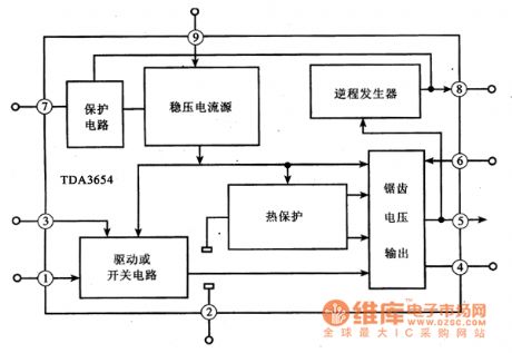
The TDA3654 is designed as one kind of field scanning output integrated circuit that is produced by the PHILIPS company, and it can be used in the domestic and imported color TVs.
1.Features
The maximum output current of the TDA3654 integrated circuit is 2.2Ap-p, the maximum output power is 15W. The internal circuit block diagram is as shown in figure 1. This IC can be directly used as the substitute of the TDA3653B and TDA3653C.
Figure 1 The internal circuit block diagram of the TDA3654 integrated circuit
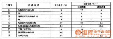
2.Pin functions and data
The TDA3654 integrated circuit is in the 9-pin single row package, the pin functions and data is as shown in the table 1.
Table 1 The pin functions and data of the TDA3654 integrated circuit
(View)
View full Circuit Diagram | Comments | Reading(1165)
MIP0254SP micro-consumption single chip switch power supply integrated circuit
Published:2011/6/8 22:08:00 Author:Christina | Keyword: micro-consumption, single chip, switch, power supply, integrated circuit


The MPO254SP is designed as a wide voltage range micro-consumption single chip switch power supply integrated circuit, and it can be used to make all kinds of AC adapters.
1.Features
The MPO254SP is composed of the high power MOSFET (the VDS is 700V), the oscillator, the high voltage power supply and the current limiter.
2.Internal circuit block diagram and the pin functions
The MIP0254SP integrated circuit is in the 8-pin DIP package, the internal circuit block diagram is as shown in the figure, the pin functions and data is as shown in the table.
The internal circuit block diagram of the MPO254SP
The pin functions and data of the MPO254SP
3. The typical application circuit
The typical application circuit of the MP02545P is as shown in the figure.
(View)
View full Circuit Diagram | Comments | Reading(1216)
Audio monitoring system circuit
Published:2011/6/8 20:23:00 Author:Christina | Keyword: Audio, monitoring system


This audio monitoring system circuit uses the fuzzy judgment method, it continuously monitor the audio for 3 seconds every 6 seconds, the interval time and the detection time are adjustable. The working process is: If it detects the sound, the audio indicator light will turn on for 6 seconds. If it does not detect the sound signal, it will continuously monitor for 3 seconds, if there is the sound signal, the indicator light will turn on for 6 seconds, if there is no sound signal in the 3 seconds, the indicator light will turn off and it will send out the alarm for 0.5 second, after the alarm, the circuit will keep the non-detection state for 6 seconds, then repeats the above examination process. The circuit is as shown in the figure.
(View)
View full Circuit Diagram | Comments | Reading(508)
Thyristor driving circuit
Published:2011/6/8 20:33:00 Author:Christina | Keyword: Thyristor, driving

This circuit is composed of the novel pyroelectric infrared sensing specific device TDH98072. This control circuit has the advantages of simple circuit, easy to adjust and high reliability. And this device can be used to assemble other control circuits such as the anti-theft alarm, the automatic control lights and the automatic water valve.etc. The photoconductive resistance CdS uses the light resistance which is lower than l00kΩ or the dark resistance which is higher than 3.3MΩ. The pyroelectric infrared sensor PIR can use any kinds of small pyroelectric probe such as the ANM1 type. (View)
View full Circuit Diagram | Comments | Reading(947)
Oil furnace control circuit composed of the common integrated block
Published:2011/6/8 20:42:00 Author:Christina | Keyword: Oil furnace, control circuit, common, integrated block

This circuit can be used as the controller of the small oil furnace. Previous small oil furnace controller uses the integrated block of application-specific integrated block or the microcontroller, they are difficult to buy in the small and medium size cities, so the maintenance is difficult. This small oil furnace controller has the features of reliable performance, simple structure, low cost and convenient maintenance, we can use it in any kinds of oil furnaces by changing the connection mode. (View)
View full Circuit Diagram | Comments | Reading(587)
All-round tracking solar electronics circuit
Published:2011/6/8 21:01:00 Author:Christina | Keyword: All-round, tracking, solar, electronics
Working principle: the solar device which uses the photovoltaic cells needs to have the sun tracking function, or the efficiency will be greatly reduced. Here we introduce the device, you can track the horizontal and vertical direction of the sun by using it, at night it will automaticly reset. If you want to track the sun, you need the sun light probe. As the figure shows, the sun light probe of this device is composed of a convex lens, five photoconductive resistances, a control circuit board and a cylinder.
(View)
View full Circuit Diagram | Comments | Reading(770)
Camera internal flash circuit
Published:2011/6/8 21:16:00 Author:Christina | Keyword: Camera, internal, flash circuit

This circuit is composed of the light measurement circuit and the flash circuit, as the figure shows. It can be used in the POPTICS (one kind of popular integration camera), the Franka X-500 and the WIZEN-860S cameras. It is composed of the following circuits:
(1)the light measurement circuit is composed of the VT1, VT2 and the light metering component RG (use the cadmium sulphide CdS photoconductive resistance).
(2)the electrical inductance three-point oscillator circuit is composed of the VT3, C1, T1, this circuit completes the transformation of DC low voltage→AC high voltage→DC high voltage to supply power for the flash light.
Components selection: the VT1 and VT2 use the C945 type transistor; the VT3 uses the D965 type transistor. The LEDl uses the Φ55mm red LED, the LED2 uses the Φ55mm green LED and the LED3 uses the Φ55mm yellow LED. The RG uses the CdS photoconductive resistance. The other components are as shown in the figure. (View)
View full Circuit Diagram | Comments | Reading(3090)
TCO2/TCO3 type temperature sensor typical application circuit
Published:2011/6/8 21:29:00 Author:Christina | Keyword: temperature sensor, typical application
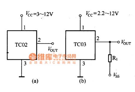
The TCO2/TCO3 type temperature sensor typical application circuit is as shown in the figure 26-11. When the TCO3 temperature sensor is used in the temperature measurement of lower than 0℃, you need to add the negative power supply Vss and the current limiting resistor R1 to the circuit, so the negative power supply's output current is 50μA, so R1=VSS/5OμA.
Figure:TCO2/TCO3 type temperature sensor typical application circuit (View)
View full Circuit Diagram | Comments | Reading(713)
TCO2/TCO3 type temperature sensor encapsulation mode circuit
Published:2011/6/8 21:30:00 Author:Christina | Keyword: temperature sensor, encapsulation mode

Figure:TCO2/TCO3 type temperature sensor encapsulation mode circuit (View)
View full Circuit Diagram | Comments | Reading(675)
TDA3504 G-Y chromatism matrix and base-color signal matrix integrated circuit
Published:2011/6/8 21:39:00 Author:Christina | Keyword: G-Y, chromatism matrix, base-color, signal, matrix, integrated circuit

The TDA3504 is designed as one kind of G-Y chromatism matrix and base-color signal matrix integrated circuit that is produced by the PHILIPS company, and it can be used in the domestic and imported large screen multi-standard color TVs.
1.Features
The TDA3504 has: the three-color matrix circuit, the 3-way signal switching circuit, the 3-way contrast control circuit, the 3-way brightness control circuit, the 3-way clamp circuit, the Y (brightness) signal amplification circuit, the brightness vanishing excitation circuitry, the selective passing and amplitude limit circuit.etc.
Figure 1 The internal circuit block diagram of the TDA3504 integrated circuit
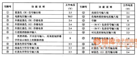
2.Pin functions and data
The TDA3504 integrated circuit is in the 20-pin double-row DIP package, the pin functions and data is as shown in table 1.
Table 1 The pin functions and data of the TDA3504 integrated circuit
(View)
View full Circuit Diagram | Comments | Reading(721)
ML8204 electronic bell integrated circuit
Published:2011/6/8 21:55:00 Author:Christina | Keyword: electronic bell, integrated circuit


The ML8204 is designed as one kind of electronic bell integrated circuit, and it can be used in the communication equipments as the ring, such as the cordless telephone and the corded phone.etc.
1.Features
The ML8204 has the ringing drive signal generation circuit and the ring signal drive circuit.etc, and it produces two alternate output audio electronic ringing. The internal circuit block diagram is as shown in figure (a). The pin functions and data is as shown in the table.
The pin functions and data of the ML8204
2.Typical application circuit
The typical application circuit of the ringing circuit which is composed of the ML8204 integrated circuit is as shown in the figure (b).
The typical application circuit of the ringing circuit which is composed of the ML8204 integrated circuit (View)
View full Circuit Diagram | Comments | Reading(1668)
Logic Status Probe Circuit
Published:2011/5/21 1:50:00 Author:Robert | Keyword: Logic Status, Probe

This circuit is used in the application cases where has low repeating frequency and also has very narrow single pulses. For example, the computer's interface and logic control system's signals. The monostable circuit change the pulses as norrow as 50ns to be extended, so that the LED's lighting or not can be seen clearly. If the under-test circuit's stable status is low voltage level, and K1 is put at low position, the CR1 would light. If it is put at high position and the circuit's stable status is high voltage level, the CR2 would light. The other two LED means the pulse signals in the stable signals.
(View)
View full Circuit Diagram | Comments | Reading(605)
Amplifier Of Big Shaft And Small Current Circuit
Published:2011/5/21 1:23:00 Author:Robert | Keyword: Amplifier, Big Shaft, Small Current

The Amplifier Of Big Shaft And Small Current Circuit is shown in the picture below.
The picture (c) circuit's output stage only uses one transistor to make up a emitter follower. The transistor's current magnification times are about 75 times. The operational amplifier's maximum consuming current is 20mA and it can control the output curent of 1.5A.
(View)
View full Circuit Diagram | Comments | Reading(475)
Faw Toyota-Crown electric starting and charging system diagram
Published:2011/6/5 21:40:00 Author:Seven | Keyword: Toyota-Crown, electric starting and charging system

View full Circuit Diagram | Comments | Reading(2786)
Telephone inline switching equipment circuit
Published:2011/6/5 22:13:00 Author:John | Keyword: Telephone inline switching equipment

Telephone inline switching equipment circuit is shown below.
(View)
View full Circuit Diagram | Comments | Reading(562)
Video monitor circuit
Published:2011/6/8 2:42:00 Author:Christina | Keyword: Video, monitor


The monitor's wireless remote control circuit uses the T2078 receiving module, and it has the 100m four buttons launch mobile phone. The remote control mobile phone has four buttons, when you press button A, the number 1 camera starts working, the video signal is transmited to the displayer through the control circuit and the electric cable to show the situation of the monitoring point 1; when you press button B, the number 2 camera starts working and shows the situation of the monitoring point 2 on the displayer; when you press the button C, the number 1 and number 2 cameras work at the same time, the two channels of video signals were sent to the displayer respectively under the action of the video control circuit, the monitors alternately shows the situations of the monitoring point 1 and 2; when you press the button D, the cameras stop working.
1.Power supply
2.Camera shooting, video control and signal compensation circuit
3.Display control circuit
(View)
View full Circuit Diagram | Comments | Reading(1169)
Field-effect transistor RSS050P03、RSS070P05 internal circuit
Published:2011/6/6 0:36:00 Author:John | Keyword: Field-effect transistor

Field-effect transistor RSS050P03、RSS070P05 internal circuit is shown in the following.
(View)
View full Circuit Diagram | Comments | Reading(836)
Fujitsu computer-style electromagnetic cooker circuit (1H ~ 1000H (700 ~ 1300W)
Published:2011/6/6 0:38:00 Author:John | Keyword: electromagnetic cooker

Fujitsu computer-style electromagnetic cooker circuit (1H ~ 1000H (700 ~ 1300W) is shown in the following.
(View)
View full Circuit Diagram | Comments | Reading(755)
camera photometer circuit
Published:2011/6/5 9:09:00 Author:John | Keyword: camera photometer

According to changes in light intensity, light current changes. When 3DG6 base injection current changes, the current in the collector circuit also changes after amplification. It would be reflected by the MA's meter bottom-up. And the meter reflects the light illumination.
When there is weak light, the base potential is close to 6V. 3DG6 is saturated to conduct, leading the collector current to fill the meter’s scale. When there is strong light, the base potential decreases to have a decreased injection current. And the collector current follows down to lead the meter to zero state. Darken photodiodes can make an mA full-scale meter by adjusting R1 and R3.
(View)
View full Circuit Diagram | Comments | Reading(716)
VGA color display ENVISION CM-335F type power supply circuit
Published:2011/6/5 9:57:00 Author:John | Keyword: color display

VGA color display ENVISION CM-335F type power supply circuit is shown below.
(View)
View full Circuit Diagram | Comments | Reading(532)
| Pages:1813/2234 At 2018011802180318041805180618071808180918101811181218131814181518161817181818191820Under 20 |
Circuit Categories
power supply circuit
Amplifier Circuit
Basic Circuit
LED and Light Circuit
Sensor Circuit
Signal Processing
Electrical Equipment Circuit
Control Circuit
Remote Control Circuit
A/D-D/A Converter Circuit
Audio Circuit
Measuring and Test Circuit
Communication Circuit
Computer-Related Circuit
555 Circuit
Automotive Circuit
Repairing Circuit