
Circuit Diagram
Index 1803
Energy-efficient motorcycle regulating rectifier circuit
Published:2011/5/23 21:30:00 Author:John | Keyword: motorcycle regulating rectifier

Motorcycles are generally powered by magneto of the car. Output voltage of Magneto is regulated by regulating rectifier to supply electric appliances on the car and to charge the battery. At present, parallel switching regulating rectifier are widely used in many domestic motorcycles, just shown in Figure 1. The device takes effects when the output voltage of magneto is over the rated voltage. The device takes effects when the output voltage of magneto is over the rated voltage. The thyristor rectifier SCR1 and SCR2 inside of SCR rectifier voltage regulator opens to clip the output voltage of magneto, achieving the voltage regulation.
(View)
View full Circuit Diagram | Comments | Reading(4845)
Pulse current limiting battery charger circuit
Published:2011/6/4 12:10:00 Author:John | Keyword: battery charger

Pulse current limiting battery charger circuit is shown below.
(View)
View full Circuit Diagram | Comments | Reading(6176)
Transformer feedback oscillator circuit
Published:2011/6/4 11:18:00 Author:John | Keyword: Transformer, oscillator
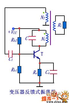
The easiest way to introduce positive feedback is to use transformer feedback method, just as shown in the figure. Replace the input voltage of the feedback voltage. And transformer feedback oscillator circuit is achieved.
Circuit Analysis: ★ Observe the circuit to find that there are amplifier, frequency selective network, positive feedback network and amplitude part achieved by nonlinear characteristics of used transistors;★ Determine whether amplifier circuit is normal or not. Amplification circuit shown in the circuit is the typical operating point stabilizing circuit, which can be used to set the appropriate static operating point; ★ Exchange pathway shown in the figure indicates that there is no open or short circuit during the signal exchanging process. And the circuit can be amplified normally;★ Use instantaneous polarity method to determine whether the circuit is able to meet equilibrium conditions or not (specific approach). (View)
View full Circuit Diagram | Comments | Reading(1239)
Yilaida electric bicycle battery charger circuit
Published:2011/6/4 11:36:00 Author:John | Keyword: electric bicycle, battery charger

Yilaida electric bicycle battery charger circuit is shown below.
(View)
View full Circuit Diagram | Comments | Reading(6670)
Field-effect transistor US5U1、US5U2、US5U3 internal circuit
Published:2011/6/4 11:38:00 Author:John | Keyword: Field-effect transistor

Field-effect transistor US5U1、US5U2、US5U3 internal circuit is shown below.
(View)
View full Circuit Diagram | Comments | Reading(522)
Capacitor feedback oscillator improved circuit
Published:2011/6/4 11:53:00 Author:John | Keyword: Capacitor, feedback oscillator
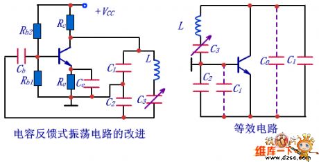
To increase the frequency of capacitor feedback oscillator circuit, it is necessary to reduce capacitance of C1 and C2 and L’s inductance. In fact, when capacitance of C1 and C2 is reduced to a certain extent, capacitor within transistor and the stray capacitors in the circuit will be incorporated into C1 and C2. Thus, the oscillator frequency can be affected. These capacitors are equivalent to input capacitor Ci and output capacitor Co in amplification circuit. The improved circuit and equivalent electrical device are shown below. Due to critical effect on capacitance by temperature and unsteady stray capacitors, it is necessary to serially set a capacitor C3 with small capacitance in the inductor branch circuit in order to stabilize the oscillation frequency. And C3 < <C1 and C3<<C2. (View)
View full Circuit Diagram | Comments | Reading(432)
Field-effect transistor UPES120P internal circuit
Published:2011/6/4 11:54:00 Author:John | Keyword: Field-effect transistor

Field-effect transistor UPES120P internal circuit is shown below.
(View)
View full Circuit Diagram | Comments | Reading(601)
adjustable frequency selection network circuit
Published:2011/6/4 12:08:00 Author:John | Keyword: selection network
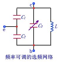
Output voltage of the capacitor feedback oscillator circuit has a good waveform. But if the oscillation frequency is adjusted by changing the capacitance, the feedback factors and the starting conditions for the circuit would be affected. And it is rather difficult to adjust the oscillation frequency by changing the inductance method. It is generally used occasions within a fixed oscillation frequency. When oscillation frequency is adjustable within a not wide range, the circuit as shown in the right figure can be used as a frequency selection network circuit. (View)
View full Circuit Diagram | Comments | Reading(390)
The LEV tester circuit of the resistor set high/low electric detecting threshold
Published:2011/6/7 1:57:00 Author:qqtang | Keyword: LEV tester, detecting threshold
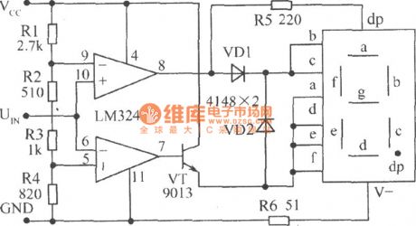
In the figure is the LEV tester circuit of the resistor(R1~R4) set high/low electric detecting threshold. The threshold voltage can be calculated by voltage distributing formula, when the value is adapted by R1~R4, the LEV threshold of 9-pin is 2.5v, the LEV threshold of 5-pin is 0.8v. When UIN≤0.8V, 7-pin outputs a high LEV, TV is conducting, the it indicates 0 ; when UIN≥2.3V, 8-pin outputs a high LEV, and it indicates 1 , the decimal dp is glowing; when UIN inputs a clock pulse, it indicates a 0 with points; when UIN is in 0.8V~2.3V, both 7 and 8 output low LEV. (View)
View full Circuit Diagram | Comments | Reading(676)
TC9028AF-023--the integrated circuit of the remote emitter
Published:2011/6/7 1:43:00 Author:qqtang | Keyword: integrated circuit, remote emitter


TC9028AF-023 is the integrated circuit of the remote emitter produced by Toshiba, which is widely used in the remote control system of large screen color TV.1.function featuresTC9028AF-023 contains clock oscillator circuit, reset circuit, key scanning encode circuit and other additional circuit.2.pin functions and dataTC9028AF-023 is in 20-pin dual line plastic package, whose pin functions and data are listed in Table 1.Notes:in the 2-pin and 3-pin of TC9028AF-023, the oscillator circuit and the external pottery resonator form a clock oscillator circuit.
(View)
View full Circuit Diagram | Comments | Reading(651)
Lamp inrush current suppression circuit
Published:2011/6/4 12:23:00 Author:John

Inrush current is the main reason for failure of the lamp. The circuit can be used to limit such current. But when the filament reaches normal operating temperature, it can provide the lamp with a normal current. This circuit also applies to low pressure pilot lights. But as long as the voltage and current is no more than certain ratings of the transistor, any kind of light bulb can be used.
(View)
View full Circuit Diagram | Comments | Reading(871)
Field-effect transistor UM5K1N internal circuit
Published:2011/6/4 12:24:00 Author:John | Keyword: Field-effect transistor

Field-effect transistor UM5K1N internal circuit is shown below.
(View)
View full Circuit Diagram | Comments | Reading(638)
High input impedance instrumentation amplifier circuit
Published:2011/6/4 12:25:00 Author:John | Keyword: instrumentation amplifier

High input impedance instrumentation amplifier circuit is just as shown below.
(View)
View full Circuit Diagram | Comments | Reading(1627)
Field-effect transistor STG3P3M25N60 internal circuit
Published:2011/6/4 12:26:00 Author:John | Keyword: Field-effect transistor
Field-effect transistor STG3P3M25N60 internal circuit is shown below.
(View)
View full Circuit Diagram | Comments | Reading(520)
differential-input instrumentation amplifier
Published:2011/6/4 13:11:00 Author:John | Keyword: instrumentation amplifier


Differential-input instrumentation amplifier is just as shown below.
(View)
View full Circuit Diagram | Comments | Reading(4)
four-divider frequency circuit
Published:2011/6/5 2:52:00 Author:John | Keyword: four-divider frequency
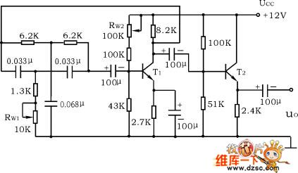
Figure: four-divider frequency circuit
Double T network RC sinusoidal oscillator circuit is shown in Figure 12-5. Disconnect the dual-T network to adjust the quiescent point of T1 pipe. And the UC1 is 6 ~ 7V. Access dual-T network and use the oscilloscope to observe the output waveform. If it does not start-up, adjust RW1 to start-up the circuit. Measure the oscillation frequency of the circuit and compare it with the calculated value. (View)
View full Circuit Diagram | Comments | Reading(560)
Hex counter circuit
Published:2011/6/5 3:16:00 Author:John | Keyword: Hex counter
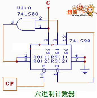
The number of two or more required to connect with cascaded 74LS90 chip. When the low chip reaches the full count, the highest point of the low chip low would be regarded as binary. And such would be sent to the CP end of a high chip.
Figure: Hex counter circuit (View)
View full Circuit Diagram | Comments | Reading(1024)
TC901--the integrated circuit of fan single chip microcomputer
Published:2011/6/7 11:08:00 Author:qqtang | Keyword: integrated circuit, single chip microcomputer


TC901 is a microcomputer integrated circuit of fan single chip produced by Toshiba, which is widely used in speed adjusting and power adjusting of all kinds of fans and household appliances.1.function featuresTC901 includes order decoding circuits, clock circuits, indicator drive circuitS, wind speed adjusting circuits and so on.2.pin functionsTC901 is in 16-pin dual in-line package, whose pin functions are shown in Figure 1.Figure 1. The pin functions of TC901
3.typical application circuitFigure 1. The typical application circuit of TC901
(View)
View full Circuit Diagram | Comments | Reading(791)
cotton machine controlling photoelectric control circuit
Published:2011/6/4 4:14:00 Author:John | Keyword: cotton machine

When the phototransistor T1 is illuminated, low resistance shows. At this time, the electric potential of point A drops and 3AX31 conducts. The relay sucks to control the cotton machine.
Capacitor of 200μF and resistor of 3 KΩ form the charging circuit, ensuring that electric potential of point A would not increase rapidly in the absence of light. The circuit plays the role of delaying and avoids the relay working too often. Resistor of 120Ω is the current feedback resistor, aiming to stabilize the operating point of 3AX31. 2CP2 is used to protect 3AX31.
(View)
View full Circuit Diagram | Comments | Reading(638)
The logic probe circuit with display function
Published:2011/6/8 2:02:00 Author:qqtang | Keyword: logic probe circuit, display function

The logic probe circuit with display functionThe circuit is shown in the circuit, it consists of a 6-backward phaser integrated circuit CD4069 and LED digit displayer. The NANDs of 1,2 and 3 form a Schmidt trigger as the logic probe, which is used to measure the logic LEV directly. The Schmidt trigger circuit is fixed with two threshold LEV, by adjusting R, we can change the LEV values of the two thresholds, so that we can judge the logic LEV of the circuit under test. The NANDs of 3,4 and 5 form a decoding circuit of strokes.
(View)
View full Circuit Diagram | Comments | Reading(1792)
| Pages:1803/2234 At 2018011802180318041805180618071808180918101811181218131814181518161817181818191820Under 20 |
Circuit Categories
power supply circuit
Amplifier Circuit
Basic Circuit
LED and Light Circuit
Sensor Circuit
Signal Processing
Electrical Equipment Circuit
Control Circuit
Remote Control Circuit
A/D-D/A Converter Circuit
Audio Circuit
Measuring and Test Circuit
Communication Circuit
Computer-Related Circuit
555 Circuit
Automotive Circuit
Repairing Circuit