Signal Processing
four-divider frequency circuit
Published:2011/6/5 2:52:00 Author:John | Keyword: four-divider frequency | From:SeekIC

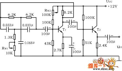
Figure: four-divider frequency circuit
Double T network RC sinusoidal oscillator circuit is shown in Figure 12-5. Disconnect the dual-T network to adjust the quiescent point of T1 pipe. And the UC1 is 6 ~ 7V. Access dual-T network and use the oscilloscope to observe the output waveform. If it does not start-up, adjust RW1 to start-up the circuit. Measure the oscillation frequency of the circuit and compare it with the calculated value.
Reprinted Url Of This Article:
http://www.seekic.com/circuit_diagram/Signal_Processing/four_divider_frequency_circuit.html
Print this Page | Comments | Reading(3)

Article Categories
power supply circuit
Amplifier Circuit
Basic Circuit
LED and Light Circuit
Sensor Circuit
Signal Processing
Electrical Equipment Circuit
Control Circuit
Remote Control Circuit
A/D-D/A Converter Circuit
Audio Circuit
Measuring and Test Circuit
Communication Circuit
Computer-Related Circuit
555 Circuit
Automotive Circuit
Repairing Circuit
Code: