
Circuit Diagram
Index 1685
TWH9312 sealed lead-acid battery charger circuit
Published:2011/6/17 6:41:00 Author:chopper | Keyword: sealed, lead-acid battery, charger circuit

The charger circuit of sealed lead-acid battery is shown as follows.It can charge one or two batteries whose value are 6V or 4Ah for one time. The part of stable voltage adopts switch type stabilized voltage supply module TWH9312,and its scope of input voltage is wide.It also includes protection circuit of over-current,short circuit inside,and it is safe and reliable.
(View)
View full Circuit Diagram | Comments | Reading(3666)
CD4069 solar energy charger circuit
Published:2011/6/17 3:00:00 Author:chopper | Keyword: solar energy, charger circuit

The solar energy charger circuit is as follows.It adopts integrated circuit CD4069(6 gate inverter,and can be replaced by 74HC04),field effect tube VT,diode VD,and some components like resistor and capacitor.The solar energy battery is set up at end A and B,and it is connected to end M,N by chargeable nickel-cadmium battery.
(View)
View full Circuit Diagram | Comments | Reading(2381)
Ten hours delay circuit
Published:2011/6/20 3:50:00 Author:TaoXi | Keyword: Ten hours, delay circuit
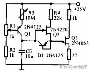
The ten hours delay circuit is as shown in the figure. The constant current source is composed of the transistor Q1 and the R1, R2, R3, the charge current can be adjusted to a few nA. The source follower is composed of Q2, the output is connected with the emitter of the single junction transistor Q3. The transistor which is connected into the diode supplies the low resistance discharging pathway to the timing capacitance. The delay time linearly changes with R3.
(View)
View full Circuit Diagram | Comments | Reading(736)
12V DC electrical motor driving current circuit
Published:2011/6/20 3:56:00 Author:TaoXi | Keyword: 12V, DC, electrical motor, driving current

The 12V DC electrical motor driving current circuit uses the 791 power operational amplifier which is in the phase-reversing connection state, the voltage gain is 10, and it can be used to drive the positive and negative rotation No.8 12V DC servo motor. The power integrated op-amp needs to add the radiator.
(View)
View full Circuit Diagram | Comments | Reading(673)
20W-60HZ servo circuit
Published:2011/6/20 4:16:00 Author:TaoXi | Keyword: 20W-60HZ, servo circuit

The 20W-60HZ servo circuit is as shown in the figure. This circuit adds two large current complementary transistors on the operational amplifier to make the servo amplifier to produce the 115V output voltage. The amplifier drives the low impedance 10V filament transformer, the primary stage and the subprime stage are reverse connected to improve the output voltage to 115V, the 115V output voltage can be used to drive the servo mechanism. The transistor needs to add the radiator.
(View)
View full Circuit Diagram | Comments | Reading(613)
degree of spoilage of food determinator circuit
Published:2011/6/14 3:18:00 Author:chopper | Keyword: degree of spoilage, food, determinator

View full Circuit Diagram | Comments | Reading(668)
28V servo power amplifier circuit
Published:2011/6/20 6:26:00 Author:TaoXi | Keyword: 28V, servo, power amplifier

The 28V servo power amplifier circuit is as shown in the figure. This circuit uses the power Darlington tube to form the common-emitter configuration, and this circuit produces the high voltage and the current gain to drive the control phase position 60Hz servo mechanism. At the same time, in the case of without the transformer, this circuit supplies the high load impedance for the pre-amplifier circuit.
(View)
View full Circuit Diagram | Comments | Reading(656)
Jinbao BC-60 multiple use charger circuit
Published:2011/6/14 3:19:00 Author:chopper | Keyword: Jinbao, multiple use, charger

View full Circuit Diagram | Comments | Reading(758)
Taiwan clairvoyance charger circuit
Published:2011/6/14 3:20:00 Author:chopper | Keyword: Taiwan, clairvoyance, charger

View full Circuit Diagram | Comments | Reading(887)
80V effective value analog switch circuit
Published:2011/6/20 7:31:00 Author:TaoXi | Keyword: 80V, effective value, analog switch
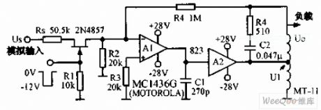
The 80V effective value analog switch circuit is as shown in the figure. In this circuit, the A1 is the operational amplifier MC1436G, A2 is the 823 type power operational amplifier, T1 is the small transformer MT11. The feedback circuit stabilizes the output signal to reduce the influence of the circuit parameters changing. The AC input signal which is changed in the range of ±10V can be turned on and off by the FET gate's -12V voltage, when the gate voltage is 0V, the switch turns on and the voltage is amplified and output by the amplification transformer. This circuit can be used in the digital same-frequency converter.
(View)
View full Circuit Diagram | Comments | Reading(563)
TA7376P dual track power amplification integrated circuit
Published:2011/6/16 1:07:00 Author:chopper | Keyword: dual track, power amplification, integrated circuit


TA7376P is a dual track power amplification integrated circuit and it is of the characteristic that quiescent current is samll,power supply noise is low,output power is big,outward elements are few and so on.The scope of the working power supply is 4.5-9V,typical working voltage is 6V.1.The inner circuit and function of pins of TA7373FThe inner circuit of TA7373F integrated package is shown as picture 1.This IC adopts single inline 9 pinned package.Its function and data of pins are shown as chart 1.
2.TA7376P typical application circuitThe typical application circuit of TA7376P integrated package is shown as picture 2.
(View)
View full Circuit Diagram | Comments | Reading(880)
400Hz driving circuit
Published:2011/6/20 7:38:00 Author:TaoXi | Keyword: 400Hz, driving circuit

The 400Hz driving circuit can be used to improve the output power of the digital/synchronous transformation system, even if the circuit use the electrical resistance load, it also can get the stable, precise output gain, this circuit has the overcurrent protection function, it can continuously output the 400Hz, 95V RMS voltage to the 500Ω load, the power bandwidth is 50 kHz. When the load current is more than 300mA, the protection circuit will turn the current back to 200mA.
(View)
View full Circuit Diagram | Comments | Reading(729)
Aiwa AC-209H charger circuit
Published:2011/6/14 3:21:00 Author:chopper | Keyword: Aiwa, charger

View full Circuit Diagram | Comments | Reading(1115)
TA7373F stereo demodulation integrated circuit
Published:2011/6/16 0:54:00 Author:chopper | Keyword: stereo, demodulation, integrated circuit
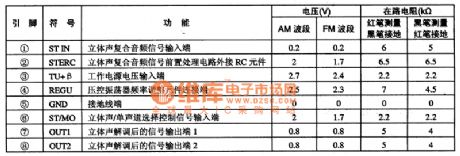
TA7373F is a stereo demodulation integrated circuit produced by Company TOSHIBA and it is applied to sound systems such as voltage walkman as FM stereo signal demodulation.1.function characteristicsTA7373F integrated circuit includes stereo signal demodulation circuit,stereo/monophony selection control circuit,stereo demodulation preamplifier circuit,frequency dividing circuit,and other miscellaneous function circuits.2.Function and data of pinsTA7373F adopts 8 pins dual inline package.And its function and data of pins of the integrated circuitare shown as chart 1.
(View)
View full Circuit Diagram | Comments | Reading(495)
555 long delay timer circuit 2
Published:2011/6/20 7:49:00 Author:TaoXi | Keyword: 555, long delay, timer

The difference between this monostable delay circuit which is composed of the 555 and the normal monostable delay circuit is the pin-5 of this circuit is connected with the power supply voltage port through the diode D1. So the 555's control port pin-5's (it is connected with the circuit's internal voltage division point 2UDD/3) threshold voltage is improved to 12V-0.7V=11.3V, this makes the charging time of the capacitance C to be extended greatly. The timing time of the figure parameters is 73 minutes. If you press the button, the 555 sets, the relay closes. After 73 minutes, the relay releases.
(View)
View full Circuit Diagram | Comments | Reading(817)
Furi F24 cassette mechanism switch power supply circuit
Published:2011/6/14 3:22:00 Author:chopper | Keyword: Furi, cassette mechanism, switch power supply

View full Circuit Diagram | Comments | Reading(821)
CMOS system power supply interface-AC switch circuit
Published:2011/6/20 19:06:00 Author:TaoXi | Keyword: CMOS, system, power supply, interface, AC, switch
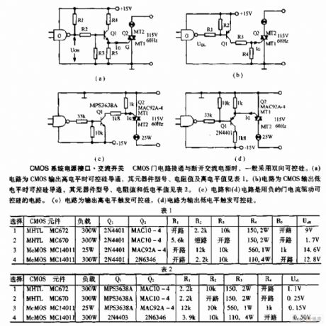
When the CMOS gate circuit turns on and turns off, the circuit usually use the two-way SCR. Circuit (a) is the SCR conduction when the CMOS outputs the high level, the component model, resistance value and the high level value is as shown in table 1. Circuit (b) is the SCR conduction when the CMOS outputs the low level, the component model, resistance value and the high level value is as shown in table 2. Circuit (c) and circuit (d) are the SCR circuits which are drived by the negative gate current. Circuit (c) is the SCR which is triggered by the output high level, circuit (d) is the SCR which is triggered by the output low level.
(View)
View full Circuit Diagram | Comments | Reading(534)
TA7291S electric motor driving integrated circuit
Published:2011/6/16 0:59:00 Author:chopper | Keyword: electric motor, driving, integrated
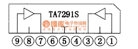
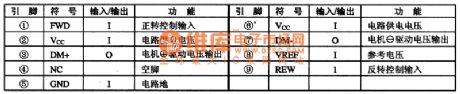
TA7291S is a bidirectional control motor driving integrated circuit produced by Company TOSHIBA.It is applied to laser player to the load motor drive.1.The inner circuitTA72915 integrated circuit includes two motor driving integrated circuits.Its inner circuit is shown as picture 1.
2.function of pinsTA72915 integrated circuit adopts 9 pins single inline package.Its functions of pins of integrated circuitare shown as chart 1.
(View)
View full Circuit Diagram | Comments | Reading(1666)
constant current battery charger of CW117/CW217/CW317 circuit
Published:2011/6/16 1:02:00 Author:chopper | Keyword: constant current, battery charger

We can produce many kinds of battery charger by using three-terminal adjustable output voltage integrated regulator.The following picture describes a constant current battery charger,This circuit is the same with constant current source.Because the resistance R is 24Ω,the output current Io=1.25/24=52mA,and charge the battery with the constant current 52mA.It can offer different charge current by changing the value of resistance R.
(View)
View full Circuit Diagram | Comments | Reading(789)
TA7232P dual audio power amplifition integrated circuit
Published:2011/6/14 3:32:00 Author:chopper | Keyword: dual audio power, amplifition, integrated circuit


TA7232P is a dual track audio power amplifition integrated circuit produced by Company TOSHIBA,and it is applied to stereo radio and tape player,music center and so on as a power amplifier.1.The inner circuit and function of pins of TA7232PTA7232P integrated package inner circuit is formed by two audio power amplifition circuits of same function.Its integrated package inner circuit and typical application circuit which forms dual track are shown as picture 1.This IC adopts 12 pins single inline package,its function and data of pins of the integrated circuit are shown as chart 1.
(View)
View full Circuit Diagram | Comments | Reading(2506)
| Pages:1685/2234 At 2016811682168316841685168616871688168916901691169216931694169516961697169816991700Under 20 |
Circuit Categories
power supply circuit
Amplifier Circuit
Basic Circuit
LED and Light Circuit
Sensor Circuit
Signal Processing
Electrical Equipment Circuit
Control Circuit
Remote Control Circuit
A/D-D/A Converter Circuit
Audio Circuit
Measuring and Test Circuit
Communication Circuit
Computer-Related Circuit
555 Circuit
Automotive Circuit
Repairing Circuit