
Circuit Diagram
Index 1688
Nissan A32-EL warning lamp circuit 1
Published:2011/6/22 10:20:00 Author:Nancy | Keyword: Nissan, warning lamp

View full Circuit Diagram | Comments | Reading(383)
IF amplifier IC circuit
Published:2011/6/19 4:47:00 Author:John | Keyword: IF amplifier

The picture shows a basic circuit composed of IF amplifier module. If a local reception of AM receiver is needed, the first-level circuit is only needed. For receivers with short-wave or other needed high-sensitivity, two or three circuits are needed to increase the gain. Each level of the gain requires 50dB and some projects may require 80 ~ 110dB.
IF amplifier module is constructed based MC-1350P gain module chip (the chip can also replace NTE-746 in the NTE). (View)
View full Circuit Diagram | Comments | Reading(1664)
Simple voltage maintainer circuit
Published:2011/6/21 7:14:00 Author:TaoXi | Keyword: Simple, voltage maintainer

In the figure, the IC uses the general type integrated operational amplifier such as the UA741, and the operational amplifier is connected into the 1:1 voltage follower, the input impedance is very high, but the gain is 1, actually it plays the impedance transformation function. If you connected a capacitance C1 at the in-phase input port of IC, the C1 is called the test holding capacitor. When the test meter or test pen is connected with the test point, the voltage of test point charges the test holding capacitor C1, after about 1 second, the C1 is charged to the measured voltage. When the test meter or test pen is removed from the test point, C1 discharges through the input impedance of integrated operational amplifier.
(View)
View full Circuit Diagram | Comments | Reading(598)
OPA676 programmable gain amplification circuit
Published:2011/6/20 5:37:00 Author:John
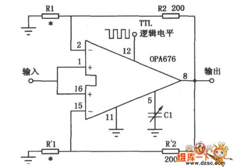
OPA676 programmable gain amplification circuit is shown.
(View)
View full Circuit Diagram | Comments | Reading(427)
Low-frequency amplification feedback circuit
Published:2011/6/20 5:48:00 Author:John

Low-frequency amplification feedback circuit is shown.
(View)
View full Circuit Diagram | Comments | Reading(488)
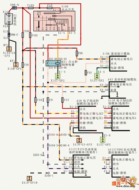
Shanghai Buick Royaum V63.6L car power grounding distribution circuit diagram
Published:2011/6/24 4:32:00 Author:Nicole | Keyword: Shanghai Buick Royaum, car, power grounding, distribution
View full Circuit Diagram | Comments | Reading(441)
Analog quantity input signal regulating circuit
Published:2011/6/21 8:31:00 Author:TaoXi | Keyword: Analog quantity, input signal, regulating circuit
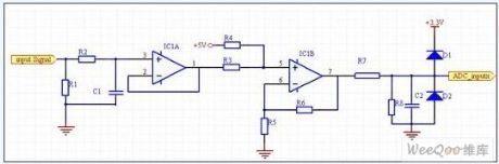
The data acquisition circuit is mainly responsible for the conversion of the analog signals such as the voltage and current. Because the detected voltage and current quantity value is large, the value is far more than the allowed input signal range of DSP, so we need to reduce the value of these analog signals, and change the current quantity into the voltage quantity, also we need to change the dual-polarity signal into the single-polarity signal, and match the level, the A/D is sent into the DSP for operating. The realization method is summarized as follow: the voltage and current signals are converted by the current model Hall sensor, and form the voltage signal which is proportional to the original signal on the high precision sampling resistance.
(View)
View full Circuit Diagram | Comments | Reading(439)
LM1036 + TDA1521 simplest high-quality power amplifier circuit
Published:2011/6/21 0:11:00 Author:John | Keyword: amplifier

LM1036 + TDA1521 simplest high-quality power amplifier circuit is shown.
(View)
View full Circuit Diagram | Comments | Reading(7828)
NE-602 varactor tuning input circuit
Published:2011/6/21 0:12:00 Author:John | Keyword: varactor

NE-602 varactor tuning input circuit is shown.
(View)
View full Circuit Diagram | Comments | Reading(849)
TDA1517 amplifier circuit
Published:2011/6/21 0:10:00 Author:John | Keyword: amplifier
TDA1517 amplifier circuit is shown.
(View)
View full Circuit Diagram | Comments | Reading(7234)
High efficiency white LED driving circuit uses the single-cell lithium battery as the power
Published:2011/6/21 8:47:00 Author:TaoXi | Keyword: High efficiency, white LED, driving circuit, single-cell, lithium battery
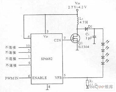
The white LED driving circuit is composed of the white LED driver and the external circuits (includes the transistor, the diode, the inductor, the capacitor and the resistor). The white LED driving circuit needs a constant current source, the current is 15mA~20mA. The luminance of the LED depends on the positive current, so we use some white LEDs in series to ensure every white LED has the same current. The four series white LEDs need 14V voltage, by using the step-up voltage stabilizer to promote the operating voltage of the single-cell lithium battery (2.7V~4.2V), we can get this 14V voltage. The high efficiency white LED driving circuit that uses the single-cell lithium battery (2.7V~4.2V) as the power is as shown in the figure.
(View)
View full Circuit Diagram | Comments | Reading(858)
TDA2030A amplifier circuit
Published:2011/6/21 0:11:00 Author:John | Keyword: amplifier

TDA2030A amplifier circuit is shown.
(View)
View full Circuit Diagram | Comments | Reading(8081)
Large current adjustable voltage stabilization power supply circuit
Published:2011/6/22 1:48:00 Author:TaoXi | Keyword: Large current, adjustable, voltage stabilization, power supply


Circuit and working principle
The pin figure of the TL413 is as shown in figure 1, the typical application of the TL413 is as shown in figure 2, the output voltage of pin-2 and pin-3 are V=2.5(R2十R3)V/R3. If we change the resistance value of R2, we can change the output reference voltage. Figure 3 shows the output current (about 6A) that is composed of the voltage reference and the regulator (the TL413 drives the external FET K790), this circuit is simple and safe.
The voltage regulation process: when the output voltage reduces, the electric potential of point f reduces, this potential is amplified by the T1431 to increase the voltage of point e, and it is adjusted by the K790, the electric potential of point b rises; on the contrary, when the output voltage rises, the electric potential of point f rises too, the electric potential of point e reduces, and it is adjusted by the K790, the electric potential of point b reduces.
(View)
View full Circuit Diagram | Comments | Reading(2342)
40W fluorescent lamp electronic ballast circuit
Published:2011/6/21 0:11:00 Author:John | Keyword: fluorescent lamp, electronic ballast

40W fluorescent lamp electronic ballast circuit is shown.
(View)
View full Circuit Diagram | Comments | Reading(19005)
Switch power supply start-up circuit with the MOSFET
Published:2011/6/22 1:51:00 Author:TaoXi | Keyword: Switch, power supply, start-up, MOSFET

Switch power supply start-up circuit with the MOSFET (View)
View full Circuit Diagram | Comments | Reading(1911)
Switch power supply start-up circuit with the transistor
Published:2011/6/22 1:52:00 Author:TaoXi | Keyword: Switch, power supply, start-up, transistor

The Switch power supply start-up circuit with the transistor is as shown in the figure:
(View)
View full Circuit Diagram | Comments | Reading(1019)
Mazda 94THUNDERBIRD electric seat lumbar circuit
Published:2011/6/21 0:13:00 Author:John | Keyword: electric seat

Mazda 94THUNDERBIRD electric seat lumbar circuit is shown. (View)
View full Circuit Diagram | Comments | Reading(645)
Three-phase no inverter UPS circuit charged by the two groups of battery and single pipe half-wave rectifier
Published:2011/6/22 1:55:00 Author:TaoXi | Keyword: Three-phase, no inverter, UPS, two groups, battery, single pipe, half-wave, rectifier

The Three-phase no inverter UPS circuit which ischarged by the two groups of battery and single pipe half-wave rectifier is as shown in the figure:
(View)
View full Circuit Diagram | Comments | Reading(4592)
Single-phase no inverter UPS circuit charged by the two groups of battery and single pipe half-wave rectifier
Published:2011/6/22 1:57:00 Author:TaoXi | Keyword: Single-phase, no inverter, UPS, two groups, battery, single pipe, half-wave, rectifier

The Single-phase no inverter UPS circuit which ischarged by the two groups of battery and single pipe half-wave rectifier is as shown in the figure:
(View)
View full Circuit Diagram | Comments | Reading(1044)
Mazda 94THUNDERBIRD (4.6L) transmission circuit
Published:2011/6/21 0:14:00 Author:John | Keyword: transmission

Mazda 94THUNDERBIRD (4.6L) transmission circuit is shown.
(View)
View full Circuit Diagram | Comments | Reading(579)
| Pages:1688/2234 At 2016811682168316841685168616871688168916901691169216931694169516961697169816991700Under 20 |
Circuit Categories
power supply circuit
Amplifier Circuit
Basic Circuit
LED and Light Circuit
Sensor Circuit
Signal Processing
Electrical Equipment Circuit
Control Circuit
Remote Control Circuit
A/D-D/A Converter Circuit
Audio Circuit
Measuring and Test Circuit
Communication Circuit
Computer-Related Circuit
555 Circuit
Automotive Circuit
Repairing Circuit