
Circuit Diagram
Index 1693
The ultra-high frequency emitting module CS901 circuit composed of SAW
Published:2011/6/26 21:20:00 Author:Borg | Keyword: ultra-high frequency, emitting module
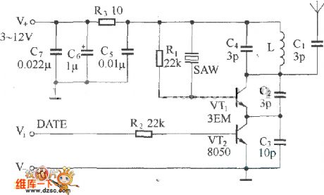
Figure:The ultra-high frequency emitting module CS901 circuit composed of SAW In the figure is the ultra-high frequency emitting module CS901 circuit composed of SAW, the model of the circuit is CS901, which adds the modulator VT2 and the power supply filter circuit on the base of basic circuits. The capacitors C5~C7 and R3 compose the power supply filter circuit, which avoid the disturbance of the power supply and improve the stability of the circuit. VT2 and R2 compose the modulation circuit, which is fixed at the emitting pole of the oscillating emitter VT1, the data signal is input from V1, by the control on VT2, the digital modulation of the emitting signal is completed. (View)
View full Circuit Diagram | Comments | Reading(729)
The thyristor switch circuit of the serial photoelectric coupler control
Published:2011/6/26 21:29:00 Author:Borg | Keyword: thyristor switch, photoelectric coupler

The gas-fog alarm circuit of dual-way thyristors When there is the combustible, the conductance of the TGS308 gas sensor is increasing, and it picks out the voltage with the help of potentiometer RP1, the value of the voltage is from 3V to 20V. The raised voltage is then added on transistor VT1 by the diode and the 4.7kΩ resistor, so VT1 is conducting, which makes the dual thyristor 2N6070A conducting. Because of what described above, the full-wave AC voltage pushes H to generate the sound of 90dB, fulfilling the alarm. H is the 24V AC alarm of Deltal6003168.
(View)
View full Circuit Diagram | Comments | Reading(498)
A low-cost but precise temperature test circuit
Published:2011/6/26 21:40:00 Author:Borg | Keyword: low-cost, precise, temperature test circuit


With 3DG6 as the temperature sensor, the test amplifier composed of the LM324 op-amp is shown in figure 1. The transistor 3DG6 is located in the test spot, and its basic pole is short with its collecting electrode, i.e the emitting positive bias, the collecting knot 0 bias is used as the temperature sensor, the power supply provides with 45mA collecting electrode current for 3DG6 with the help of resistor R1 (100K). Its UBE is connected with the non-inverting terminal of LM324, all R1, R2, R3 and R4 are ordinary metal film resistors, if R2=R3,the output of the amplifier will be U0≈2UBE. In the device, both the 2 chips of LM324 can detect the input signal of 7 lines.
(View)
View full Circuit Diagram | Comments | Reading(698)
The 0~35V regulated power supply circuit
Published:2011/6/25 5:29:00 Author:Borg | Keyword: regulated power supply

View full Circuit Diagram | Comments | Reading(605)
The simple square wave oscillator circuit
Published:2011/6/25 5:31:00 Author:Borg | Keyword: square wave, oscillator
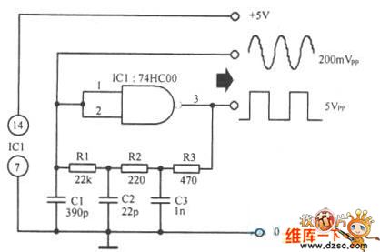
The simple square wave oscillator circuit is shown in the figure.
(View)
View full Circuit Diagram | Comments | Reading(760)
The TDA7294 audio amplifier circuit
Published:2011/6/26 5:22:00 Author:Borg | Keyword: audio amplifier

The TDA7294 audio amplifier circuit is shown as above.
(View)
View full Circuit Diagram | Comments | Reading(1713)
The time delay over-voltage alarm circuit of the AC regulator
Published:2011/6/26 21:50:00 Author:Borg | Keyword: time delay, over-voltage alarm, AC regulator

In the figure is the time delay over-voltage alarm circuit of the AC regulator. The alarm consists of the high-voltage time delay circuit, over-voltage detection and alarm circuit, output control circuit and so on. The output circuit consists of the controllable silicon SCR, relay J0 and D7. The high-voltage time-delay circuit is a time delay oscillating circuit composed of 555, R7 and C4. When the AC power supply is on, as the voltage on C4 can't mutate, the 2-pin is in a low LEV and the 555 3-pin is outputting a high LEV, which makes BG1 conducting.
(View)
View full Circuit Diagram | Comments | Reading(1607)
The 0~50V regulated power supply circuit
Published:2011/6/26 5:32:00 Author:Borg | Keyword: regulated, power supply

View full Circuit Diagram | Comments | Reading(1215)
The basic wireless emitter circuit composed of SAW oscillators
Published:2011/6/26 21:13:00 Author:Borg | Keyword: basic, wireless, emitter circuit

Figure: The basic wireless emitter circuit composed of SAW oscillators (a) is the transistor ultra-frequency wireless emitting basic circuit, of which SAW is connected on the basic pole of the triode VT as the forward feedback and it is in parallel connection with LC net. (b) is another transistor ultra-frequency wireless emitting basic circuit composed of the SAW oscillator, in which the SAW is fixed between the basic pole and emitting pole of the transistor, and the phase relationship between them is 180o, which satisfy the phase requirement of oscillating. (View)
View full Circuit Diagram | Comments | Reading(2754)
The voltage control non-linear function oscillator circuit
Published:2011/6/26 22:06:00 Author:Borg | Keyword: voltage control, non-linear function, oscillator

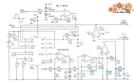
The voltage control non-linear function oscillator circuit is shown in the figure.
(View)
View full Circuit Diagram | Comments | Reading(451)
The multi-way touch stereo alarm circuit
Published:2011/6/27 20:06:00 Author:Borg | Keyword: multi-way, touch stereo alarm

In the figure is the multi-way touch stereo alarm circuit. This circuit consists of the power supply switch circuit, stereo circuit, touch alarm display circuit and so on, which can be used to secure and monitor 6 spots. The power supply switch circuit composes of BG1~BG4, the stereo circuit consists of IC1 and IC2, the touch alarm display circuit consists of the diodes D1~D6, the phase reverser, LED1~LED6, and IC1, R5, W1 and C2 compose the non-stable multi-resonance oscillator, the oscillating frequency is f=l.44/(R5+2Rw1)C2, the regulating potentiometer W1 makes the frequency at 1Hz or so.
(View)
View full Circuit Diagram | Comments | Reading(1130)
The sound control duty alarm circuit
Published:2011/6/26 22:16:00 Author:Borg | Keyword: sound control, duty alarm

In the figure is the sound control duty alarm circuit. The alarm consists of the DC regulated power supply, timing switch circuit and sound control pulse generator. In the circuit, S is the microphone, which converts the step sound and other sounds into the electric signals, and the signals are added on the trigger terminal 2-pin of the 555 time-based circuit. 555, R6 and C2 compose a single steady trigger, the adjusting resistor R6 makes the voltage on 2-pin a little higher than 1/3VDD. The 3-pin of 555 outputs a low LEV. When there's something happening, BG2 is outputting a passive pulse of certain amplitude, which reverses 555.
(View)
View full Circuit Diagram | Comments | Reading(459)
The protection circuit diagram adopted transistor triode
Published:2011/6/24 4:08:00 Author:Nicole | Keyword: protection, transistor, triode

The protection circuit which adopts transistor triode, the regulator's amperage is limited by using the triode's emitter junction slot, the protection circuit's position can be setin the front or back of adjustment, it depends on the used PNP type or NPN type, in the figure, the protection circuit is made of VT1 and RS.
(View)
View full Circuit Diagram | Comments | Reading(516)
The time delay alarm circuit
Published:2011/6/26 21:59:00 Author:Borg | Keyword: time delay alarm

In the figure is the time delay alarm circuit. The alarm consists of 2 NE555 timers, a relay, a ring and a switch circuit, etc. When the switch K1 is closed, the first NE555 alarm is going to making sounds in 20s or so, which controls the working of the 2nd NE555. The second NE555 makes sounds for about 60s. The time delay of about 20s is for the following purposes: first, letting the thief think he is safe, so people can seize him in the basement; second, letting the owner have enough time to reset the switch.
(View)
View full Circuit Diagram | Comments | Reading(1029)
The remote control emitting circuit composed of TX4915
Published:2011/6/26 22:00:00 Author:Borg | Keyword: remote control, emitting circuit
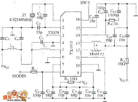
Figure: The remote control emitting circuit composed of TX4915 (View)
View full Circuit Diagram | Comments | Reading(449)
The SF05A/B emitter circuit
Published:2011/6/26 8:21:00 Author:Borg | Keyword: emitter circuit
Figure:The SF05A/B emitter circuit
SF05A/B can work with SJ05B,SJ04E and SJ04H, and the emitting efficiency of the circuit is relevant to the working voltage, aerial and R2. (View)
View full Circuit Diagram | Comments | Reading(389)
The phase-lock function oscillator circuit
Published:2011/6/26 22:35:00 Author:Borg | Keyword: phase-lock, function oscillator
The phase-lock function oscillator circuit is shown in the figure.
(View)
View full Circuit Diagram | Comments | Reading(687)
The amplifier circuit of audio control and soft switch
Published:2011/6/27 19:32:00 Author:Borg | Keyword: amplifier circuit, audio control, soft switch

Soft switch is the configuration of the emitting pole follower that adopts the BD131 transistor as the switch. Collection is the wiring permanent power supply voltage, the conductor of the second half year series can only remove the noise of the power supply. Therefore, the conductor is not very important, which can be omitted, if the DC power supply is smooth enough. The control power supply is used in BD131 base harbour, the 10u capacitor and the 10K resistor have double functions: 1. One of them is responsible to that the 10u capacitor makes sure the switch transistor provides with power from 0v linearly, and the LED1 is fixed on the amplifier accordingly. (View)
View full Circuit Diagram | Comments | Reading(774)
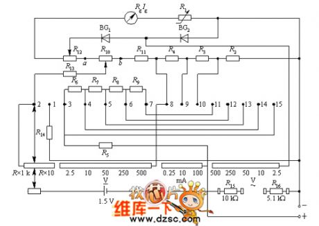
MF27-2 multimeter circuit diagram
Published:2011/6/24 4:10:00 Author:Nicole | Keyword: multimeter
View full Circuit Diagram | Comments | Reading(950)
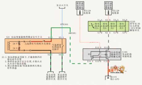
Shanghai Buick Royaum V63.6L car automatic transmission control circuit diagram(2)
Published:2011/6/24 4:14:00 Author:Nicole | Keyword: Shanghai Buick Royaum, car, automatic transmission
View full Circuit Diagram | Comments | Reading(387)
| Pages:1693/2234 At 2016811682168316841685168616871688168916901691169216931694169516961697169816991700Under 20 |
Circuit Categories
power supply circuit
Amplifier Circuit
Basic Circuit
LED and Light Circuit
Sensor Circuit
Signal Processing
Electrical Equipment Circuit
Control Circuit
Remote Control Circuit
A/D-D/A Converter Circuit
Audio Circuit
Measuring and Test Circuit
Communication Circuit
Computer-Related Circuit
555 Circuit
Automotive Circuit
Repairing Circuit