
Circuit Diagram
Index 1698
12V DC changed into 100V AC inverter power supply circuit
Published:2011/6/21 20:41:00 Author:TaoXi | Keyword: 12V, DC, 100V, AC, inverter, power supply

The inverter uses the power field effect transistor as the inverter device. This device uses the car battery as the supply power. So the input voltage is 12V DC. The output voltage is the 100V AC. But the input voltage and the output voltage are not limited to this. You can use any voltage. They depends on the transformer. The waveform output is the square wave. According to the experience, this circuit has the power of 100W. This circuit must be installed the fuse, because if there is too much input current, the oscillator will stop.
(View)
View full Circuit Diagram | Comments | Reading(1977)
Minitype 5V to 12V boost converter circuit
Published:2011/6/21 20:49:00 Author:TaoXi | Keyword: Minitype, boost, converter, 5V, 12V

Another typical application of the LT1930 is as shown in the figure, it is the 5V to 12V boost converter. This circuit supplies the 300mA output current, the efficiency is as high as 87%. The maximum output voltage ripple wave of this circuit is 60mVp-p.
The LT1930 is the SOT-23 switching voltage regulator which has the highest power in the industry. It can be used in the boost converter, the SEPIC and the flyback converter. (View)
View full Circuit Diagram | Comments | Reading(2475)
Multi-purpose electronic transformer circuit
Published:2011/6/21 21:05:00 Author:TaoXi | Keyword: Multi-purpose, electronic transformer

Here we introduce one kind of electronic transformer which belongs to the switch power supply family, and it is easy to make. After repeated experiments, we know the current response of this electronic transformer is very fast. It exceeds the ordinary operating frequency transformers, so this circuit can completely replace the power amplifier. The AC/DC electronic transformer has the over-current limit protection function, so it can be used to charge the electric bicycle's battery. If we connect some AC/DC electronic transformers in parallel, we can make the high power charger. Because this circuit has great current changing adaptability, so we can use it to replace the KW AC adapter of the sound power.
(View)
View full Circuit Diagram | Comments | Reading(4797)
Three 1.2V-1.5V input and 9V output booster circuits
Published:2011/6/21 21:10:00 Author:TaoXi | Keyword: 1.2V-1.5V, input, 9V, output, booster


The three 1.2V-1.5V input and 9V output DC/DC circuits are as shown in the figure, it can be used in the boost battery circuit which uses the battery as the power supply.
(View)
View full Circuit Diagram | Comments | Reading(5262)
1.5V battery power supply 15V output DC/DC booster circuit
Published:2011/6/21 21:16:00 Author:TaoXi | Keyword: 1.5V, battery, power supply, 15V, output, DC/DC, booster

1.5V battery power supply 15V output DC/DC booster circuit (View)
View full Circuit Diagram | Comments | Reading(6135)
Reverse phase output four times voltage DC/DC voltage stabilization power supply circuit without inductance
Published:2011/6/21 22:02:00 Author:TaoXi | Keyword: Reverse phase, output, four times, voltage, DC/DC, voltage stabilization, power supply, inductance

The reverse phase output four times voltage DC/DC voltage stabilization power supply circuit which is composed of the MAX868 and CMPSH-3S is as shown in the figure. The MAX868 is designed as the voltage stabilization type reverse phase charge pump integrated circuit that produces the -2VIN output voltage, the input voltage range of the VIN is 1.8~5.5V. The IC1 adjusts the output voltage through the pulse frequency modulation (PFM), the maximum frequency is 450kHz. The quiescent current is very low (30μA). We can form a reverse phase four times voltage power supply circuit by adding the charge pump which is composed of the C3, C4 and the schottky diode to the feedback loop.
(View)
View full Circuit Diagram | Comments | Reading(667)
12V-80V/10A output DC/DC converter voltage stabilization power supply circuit
Published:2011/6/21 22:14:00 Author:TaoXi | Keyword: 12V-80V/10A, output, DC/DC, converter, voltage stabilization, power supply

The push-pull type converter circuit uses two BUZ41A SIP MOS transistors and a TDA4718 integrated circuit as the power supply of the ship power grid, the input side and the output side of the converter are isolated. The operating frequency is 50kHz, the efficiency is 75%, the power supply voltage is in the range of 56 to 100V. The output voltage is 12V, and it is rectified by the D10 and D11 full-wave rectifier, at last it is converted by the output filter Dr1, C20, C19 to become the DC.
(View)
View full Circuit Diagram | Comments | Reading(4305)
5V,3A output switch type voltage stabilization power supply circuit
Published:2011/6/22 1:32:00 Author:TaoXi | Keyword: 5V, 3A, output switch, voltage stabilization, power supply circuit


The LM2676 is designed as one kind of switch type integrated voltage stabilizer, it supplies the 3A drive capability, it has all the functions of the step-down switching voltage regulator, also it has good linearity and load regulation characteristics: it gets the high output efficiency by using a low conductivity resistance's DMOS power supply switch; it has the stationary output voltage of 3.3V, 5V and 12V.
The DC stabilized voltage power supply circuit with 8V-40V input and 5V,3A output which is composed of the LM2676 is as shown in the figure.
Pin of the LM2676
(View)
View full Circuit Diagram | Comments | Reading(1983)
Potentiometer control digital oscillator circuit
Published:2011/6/26 20:54:00 Author:TaoXi | Keyword: Potentiometer control, digital oscillator
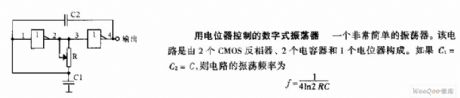
The potentiometer control digital oscillator circuit is designed as one kind of very simple oscillator that is composed of two CMOS inverters, two capacitors and a potentiometer. If C1=C2=C, the oscillation frequency of this circuit is f=1/4ln2RC.
(View)
View full Circuit Diagram | Comments | Reading(627)
Voltage control annular oscillator circuit
Published:2011/6/26 20:49:00 Author:TaoXi | Keyword: Voltage control, annular oscillator
The voltage control annular oscillator circuit changes the oscillation frequency by changing the charging and discharging voltage final value of the timing capacitance C.
(View)
View full Circuit Diagram | Comments | Reading(658)
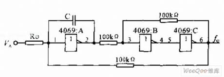
Voltage control TTL symmetric harmonic oscillator circuit
Published:2011/6/26 19:13:00 Author:TaoXi | Keyword: Voltage control, TTL, symmetric, harmonic oscillator
The voltage control TTL symmetric harmonic oscillator circuit uses the external control voltage VA to control the Inverter input voltage. The output frequency of the circuit is proportional to the VA, and it has wide adjustment range. If the VA change from 1.4V to 1.8V, the oscillation frequency is from 666KHz to 1.43MHz. The circuit (b) increases the bias resistors R1, R2 and R3, R4 than circuit (a). The D1 and D2 are the protection diodes. When the VA is from 0V to 10.5V, the frequency changes from 6.54MHz to 4.76MHz.
(View)
View full Circuit Diagram | Comments | Reading(526)
Five frequency-standard frequency standard circuit
Published:2011/6/26 20:38:00 Author:TaoXi | Keyword: Five frequency-standard, frequency standard circuit
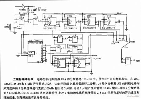
The five frequency-standard frequency standard circuit uses the DT direction cutting crystal in the NOT gate oscillator U1A and the divider chains U2-U6, and it produces the frequency standard at the frequencies of 200,100,50,25,10,5 kHz. The U2A-U3B are connected into the D trigger to produce the circuit of 2 frequency division. The U4 is the N frequency divider, the latch circuit of U5 can be used to reset the selective logic of 5 frequency division. The 100kHz output produces the symmetrical 10kHz output through the 5 and 2 frequency divisions, then the output changes into the 5kHz output through 2 frequency division. The CMOS CD4000 series logical components reduces the current of 9V battery to 2.8mA, but it still has enough switching speed and harmonic energy, and it has good phase reaction in the high frequency bands.
(View)
View full Circuit Diagram | Comments | Reading(554)
Four-phase clock source circuit
Published:2011/6/26 5:31:00 Author:TaoXi | Keyword: Four-phase, clock source circuit

The four-phase clock source circuit is composed of the synchronous mode 4 counter (74107 J-K trigger) and the decoder SN74 LS139. The output of it is the negative pulse, the pulse width is the clock interval.
(View)
View full Circuit Diagram | Comments | Reading(1393)
Voltage control oscillator circuit of the practical CMOS integrated circuit
Published:2011/6/26 4:11:00 Author:TaoXi | Keyword: Voltage control oscillator, practical, CMOS, integrated circuit
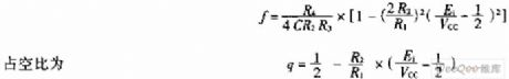
The voltage control oscillator which uses the CMOS integrated circuit always has the positive and negative power supplies, but the CMOS integrated circuit only uses one power supply. When the input voltage is 1/2 of the power supply voltage VCC, the oscillation frequency is the maximum. When the input voltage is higher than 1/2VCC or lower than 1/2VCC, the oscillation frequency is:
(View)
View full Circuit Diagram | Comments | Reading(405)
Pulse source circuit with the presetable pulse number
Published:2011/6/26 3:03:00 Author:TaoXi | Keyword: Pulse source circuit, presetable pulse number

Pulse source circuit with the presetable pulse number is composed of the controllable pulse source and the counter/pulse distributor CD4017. The output pulses is preset by the switch S2. You can clear the counter and blockade the output gate by pressing the start button S1. After the S1 opens, the oscillation source pulse outputs through the NAND gate, and the CD4017 starts counting. When it is the S2's preset position Y, the phase reversal Y controls the oscillation source to stop. So the output pulse number is the preset CP pulse number. In the figure, the switch S2 is in the position that if you press S1, the circuit will output two pulses.
(View)
View full Circuit Diagram | Comments | Reading(575)
Pulse button control annular oscillator circuit
Published:2011/6/26 2:52:00 Author:TaoXi | Keyword: Pulse, button control, annular oscillator
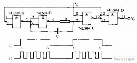
The pulse button control annular oscillator circuit is composed of the NAND gate. If the input Vi is the high level, the oscillator will start oscillating; if the Vi is low level, the oscillator will stop oscillating, the frequency of Vi is much lower than the oscillation frequency.
(View)
View full Circuit Diagram | Comments | Reading(497)
Two-channel asynchronous output waveform generator circuit
Published:2011/6/25 7:18:00 Author:TaoXi | Keyword: Two-channel, asynchronous output, waveform generator
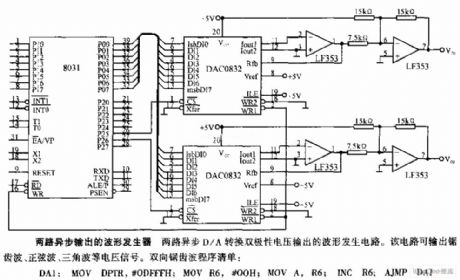
The two-channel asynchronous output waveform generator circuit is designed as one kind of waveform generator circuit that has the two channels of D/A conversion dual polarity voltage output. This circuit can output the sawtooth wave, the sine wave and the triangular wave.
(View)
View full Circuit Diagram | Comments | Reading(712)
Precise 60Hz frequency source circuit
Published:2011/6/25 6:45:00 Author:TaoXi | Keyword: Precise, 60Hz, frequency, source circuit

The precise 60Hz frequency source circuit: this circuit is composed of the CD4060 14-stage frequency divider/oscillator circuit and the CD45200 double binary to hexadecimal addition counter. This frequency source can be used in the scanning mode LED screen display clock circuit (such as the digital electric clock which is composed of the LM8560 and MM5456).
(View)
View full Circuit Diagram | Comments | Reading(845)
12.85MHZ changeable pulse width generator circuit
Published:2011/6/25 6:27:00 Author:TaoXi | Keyword: 12.85MHZ, changeable pulse, width generator
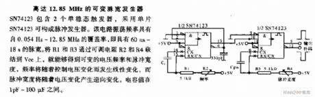
The 12.85MHZ changeable pulse width generator circuit: the SN74123 includes two monostable triggers, it uses the single chip SN74123 to form the pulse generator. The frequency range of this circuit is 0.054Hz-12.85MHz, so it has the pulse width range of 60ns-18s. If you connect the R1 and R3 to the Vcc through the adjustable resistors R2 and R4, so you get the variable voltage frequency and pulse width, the frequency will change with the control voltage, the pulse width will reversely change with the voltage. The capacitance value is in the range of 1pF-100uF.
(View)
View full Circuit Diagram | Comments | Reading(682)
Multi-tone alarm circuit
Published:2011/6/25 6:09:00 Author:TaoXi | Keyword: Multi-tone, alarm circuit

The multi-tone alarm circuit: the multi-tone alarm circuit is composed of the 555 timer, it can monitor the a, b, c, d points at the same time. In peacetime, the a, b, c, d points are connected with the ground line by wires, the 555 circuit stops working, the speaker is silent. When the invader touches off any one of the channels, the electric potential of this point will increase, the corresponding diode conducts, the 555 circuit starts oscillation, the speaker outputs the alarm. For different monitoring points, the oscillation frequencies are different too, and also the speaker tones.
(View)
View full Circuit Diagram | Comments | Reading(739)
| Pages:1698/2234 At 2016811682168316841685168616871688168916901691169216931694169516961697169816991700Under 20 |
Circuit Categories
power supply circuit
Amplifier Circuit
Basic Circuit
LED and Light Circuit
Sensor Circuit
Signal Processing
Electrical Equipment Circuit
Control Circuit
Remote Control Circuit
A/D-D/A Converter Circuit
Audio Circuit
Measuring and Test Circuit
Communication Circuit
Computer-Related Circuit
555 Circuit
Automotive Circuit
Repairing Circuit