
Circuit Diagram
Index 1683
Simple Ni-MH battery charger circuit
Published:2011/6/21 0:12:00 Author:John | Keyword: Ni-MH battery charger

Simple Ni-MH battery charger circuit is shown.
(View)
View full Circuit Diagram | Comments | Reading(2563)
bistable transconductance mixer used in NE-602 circuit
Published:2011/6/21 0:12:00 Author:John | Keyword: bistable transconductance mixer
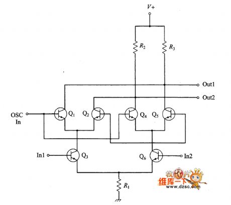
Bistable transconductance mixer used in NE-602 circuit is shown.
(View)
View full Circuit Diagram | Comments | Reading(636)
Resistor and capacitor (LC) circuit
Published:2011/6/19 3:44:00 Author:John | Keyword: Resistor, capacitor
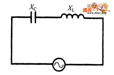
If a circuit uses both inductors and capacitors at the same time, they combine to form the inductor - capacitor (LC) resonant circuit, also known as energy storage circuit or the oscillator circuit. This circuit can be used in the radio receiver’s tuned circuits and other applications.
(View)
View full Circuit Diagram | Comments | Reading(1766)
the circuit of temperature controller(18)
Published:2011/6/23 6:25:00 Author:Ariel Wang | Keyword: temperature controller
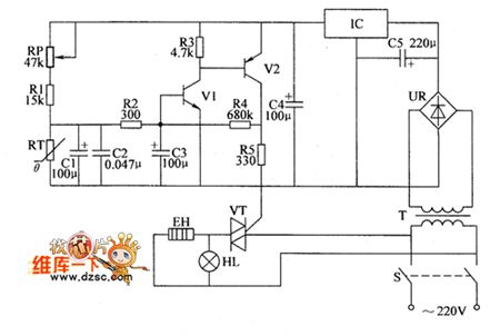
RP is used to set the temperature control point.When the resistence of RP is adjusted to a low level,the temperature control point goes up.Otherwise,the temperature control point goes down.When the temperature in thermotank is higher than the set control temperature by RP,the base voltage is lower than 0.6V.V1,V2 and V5 are all stopped.The electric heater EH stops working.HL is not lighted.When the temperature in thermotank is lower than the set control temperature by RP,the base voltage of V1 is higher than 0.6V.V1 and V2 are saturated to conduct.The output voltage of V2's collector goes to VT's gate by R5.VT is triggered to conduct.EH is conducted to heat.HL is lighted. (View)
View full Circuit Diagram | Comments | Reading(398)
ISD4004 interface module circuit
Published:2011/6/19 3:14:00 Author:John | Keyword: interface module

It can be seen from the figure that the circuit design is very simple. SPI port of ISD4004 SPI is directly connect with the microcontroller's SPI port. The ADUOUT of ISD4004 is directly connected to the audio output. A capacitor is placed on the audio output pin in order to achieve improvement of voice quality. ISD4004 audio output is connected with MICPHONE with the differential approach. ISD4004 interrupt output is pulled up through a resistor, then is connected with the microcontroller. The RAC pin of ISD4004 is for connecting with the general I / O port of MCU. As a result, the pin state can be controlled by the microcontroller.
(View)
View full Circuit Diagram | Comments | Reading(3616)
MODEM interface circuit
Published:2011/6/19 2:58:00 Author:John | Keyword: MODEM interface

MODEM module has been understand well, so the design for its interface circuit is relatively easy. Although MODEM provides many control lines, considering the simplicity of the interface design and the connection between the MODEM module and a microcontroller through the UART, two lines (TXD, RXD) connection is needed. Communication control on MODEM is implementated through software. Using software control is rather flexible and is also a good way to avoid excessive hardware signal detection.
(View)
View full Circuit Diagram | Comments | Reading(450)
MODEM power supply circuit
Published:2011/6/19 2:49:00 Author:John | Keyword: power supply

Despite of MODEM, the system is powered by 3.0V power supply. Such takes the power requirements on the hardware system with small ripple and stable voltage regulating functions into accounts. It also considers the low power consumption of hardware system. So the power part of the hardware system uses TI's TPS76330 chip, whose output current is 150mA. The system can meet current requirements. Besides, the chip has a small footprint, which can effectively save PCB board’s space. Power supply circuit is as shown in the figure.
To make the output power ripple be small, a 2.2μF and 0.1μF capacitors are set in the output section. Moreover, the other input end of the chip is also placed with a 0.1μF filter capacitor, thus reducing the disruption for the input end.
(View)
View full Circuit Diagram | Comments | Reading(528)
Various IF filters circuit
Published:2011/6/17 9:45:00 Author:John | Keyword: IF filter

Most of the gain and selectivity of superheterodyne radio receivers are provided by the intermediate frequency (IF) amplifier. Therefore, it is a amplifier with high-gain and narrow bandwidth. IF power gain is typically between 60 dB and 120dB. Scuh range depends on the specific design for the receiver. Usually it has a much narrower bandwidth than the RF amplifier. For example, SSB receiver’s bandwidth is 2.8kHz and the CW receiver’s bandwidth is 500Hz. IF amplifier's role is to provide gain and selectivity for the receiver. The selective parts are achieved by a variety of filters.
(View)
View full Circuit Diagram | Comments | Reading(490)
STR-M6833BFO4 switch power supply thick film integrated circuit
Published:2011/6/15 7:29:00 Author:chopper | Keyword: switch power supply, thick film, integrated circuit

STRM6833BFO4 is a switch power supply thick film integrated circuit produced (View)
View full Circuit Diagram | Comments | Reading(620)
Touch switch circuit
Published:2011/6/19 22:18:00 Author:TaoXi | Keyword: Touch switch

The touch switch circuit is as shown in the figure, if you use the finger to touch the pole plate, the pole plate inputs the small AC signal at the pin-8 of the double input port high precision level detector CA3089 to produce the voltage which is higher than the benchmark. In the integrated circuit, this voltage turns the memory trigger, the pin-5 has the high level. The voltage of pin-7 increases to U exponentially in 10 seconds. The 10 seconds is the maximum delay time, the long time touch can makes the circuit to oscillate between the two states of the on-off until the finger removes. The short time touch can make to load to get power, if you touch again, the load will cut off the power.
(View)
View full Circuit Diagram | Comments | Reading(621)
Touch type SCR zero-passaging switch cicuit
Published:2011/6/19 22:26:00 Author:TaoXi | Keyword: Touch type, SCR, zero-passaging, switch cicuit

The touch type SCR zero-passaging switch cicuit is as shown in the figure. This circuit is designed as the touch type timer. If you connect the touch type timer with the SCR zero-passaging switch, you can form the touch type SCR zero-passaging switch cicuit. When the human body touches the sheetmetal A, the induction signal conducts the 555. WHen the K is in the 1 position, the function is to control the outage of the equipment when the preset time is up; if K is in the 2 position, the function is to turn on the power of the equipment when the preset time is up.
(View)
View full Circuit Diagram | Comments | Reading(550)
groundwire style circuit
Published:2011/6/12 7:07:00 Author:chopper | Keyword: groundwire

Additionally,line filter which is used to control noise is connected to printed plate at the mains. And then,grounded common mode capacitor is fixed to the soleplate by screw.Lines are short and thick even if the current is not very big. On the printed plate are the lines of sunrise-style,just as the picture.Additionally,when the circuit adopts dual platen,it must switch in washer to guarantee the favorable contact.
(View)
View full Circuit Diagram | Comments | Reading(645)
STR-M6831AFO4 switch power supply thick film integrated circuit
Published:2011/6/15 7:41:00 Author:chopper | Keyword: switch power supply, thick film, integrated circuit


STRM6831AFO4 is a switch power supply thick film integrated circuit produced (View)
View full Circuit Diagram | Comments | Reading(803)
One hour timer circuit with the end switch
Published:2011/6/19 22:45:00 Author:TaoXi | Keyword: One hour, timer, end switch
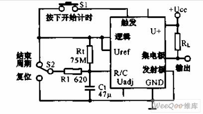
The one hour timer circuit with the end switch uses the LM122 timer and the hand control switch, the LM122 timer and the hand control switch can form the one hour timer which has the start, reset and stop functions. Once the timing begins, the S1 will not play any functions. You can pull the S2 up to finish the rated cycle, the output state will change; if you pull the S2 down, the timing capacitor voltage will be back to 0V, the output state will not change, it releases the S2 to start the new timing cycle.
(View)
View full Circuit Diagram | Comments | Reading(754)
the line of printed plate should be wide enough when process big current circuit
Published:2011/6/12 7:19:00 Author:chopper | Keyword: line, printed plate, wide, big current

The line of printed plate should be wide enough when we deal with the big current.Generally speaking,line width of 1A current should be 1mm.And we can calculate by this rate.When the current is over 10A,we can calculate by the rate 0.7A/mm.As for the bold line of the following picture,there are biggish impact current through capacitor at the moment the power supply is connected even if the current is not big.Thus,the line should be wide enough.
(View)
View full Circuit Diagram | Comments | Reading(643)
STR-M6545LF switching power supply thick film integrated circuit
Published:2011/6/15 7:31:00 Author:chopper | Keyword: switching power supply, thick film
STRM6545LF is a mixed type switching power supply thick film integrated circu (View)
View full Circuit Diagram | Comments | Reading(549)
input voltage of three-terminal integrated regulator measure circuit
Published:2011/6/15 5:44:00 Author:chopper | Keyword: input voltage, three-terminal, integrated regulator, measure

The following picture is a regulator circuit,the difference of input voltage and output voltage totally adds to the collector and emitter of controlled transistor.The output current is also the collector current of transistor.The power consumption of transistor Pc=I0 (Ui-U0),that is to say,the higher input voltage Vi is,the great power consumption of transistor is.The input voltage Uimin has to satisfy Uimin≥U0+UDROP.In the formula,UDROP is a voltage drop of the emitter and collector of transistor.Its lowest value is over the saturation voltage UCESAT of transistor.The UDROP of general regulator is about 30V,and regulator with low dropout is below 1V.
(View)
View full Circuit Diagram | Comments | Reading(673)
Digital preset circuit and the 128 buttons keypad scanning circuit
Published:2011/6/20 0:50:00 Author:TaoXi | Keyword: Digital preset, 128 buttons, keypad scanning


The digital preset circuit
The function of this circuit: it changes the keyboard pressing signal into the 2-bit BCD code and stores the code. Figure 1 is the logic diagram of this coding and storage circuit.
Keypad scanning circuit
In the last example, the keyboard scale is small, it has only ten keys (0-9). If the keyboard scale is large, by using the priority encoders to realize the coding will not economic any more. So people design the keypad scanning circuit. Figure shows the 128 keys scanning encoder.
(View)
View full Circuit Diagram | Comments | Reading(2884)
static operating point adjustment circuit
Published:2011/6/11 1:50:00 Author:chopper | Keyword: static, operating point, adjustment circuit

(1)adjustment at VC=0.5VCCUse voltmeter to measure the voltage of point K to ground and adjust R2 to make VK=0.5VCC.(2)adjustment of quiescent current IC1,IC2Minimize the resistance of RW first.when the power source is available,add sinusoidal signal to input end and use oscillograph to measure voltage waveform of load RL,and then,adjust RW until the moment that crossover distortion of output waveform disappears.
(View)
View full Circuit Diagram | Comments | Reading(589)
Time-scale circuit and the programmable frequency divider circuit
Published:2011/6/20 1:53:00 Author:TaoXi | Keyword: Time-scale, programmable, frequency divider
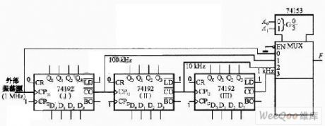

Time-scale circuit
The sequence signal generator:
Design steps: the first step is to form a model P counter; the second step is to select the appropriate data selector. You need to add the sequence which you want to produce to the data input port of the data selector in specified order, and you also need to connect the address port with the output port of the counter, the output port of the data selector will produce the sequence signal.
The programmable frequency divider: the counter can divide the frequency of the count pulse, and you can change the frequency dividing ratio by changing the mode of the counter. According to the principle, we can use the integrated counter to form the frequency divider that has the changeable frequency dividing ratio, it is the programmable frequency divider.
(View)
View full Circuit Diagram | Comments | Reading(3235)
| Pages:1683/2234 At 2016811682168316841685168616871688168916901691169216931694169516961697169816991700Under 20 |
Circuit Categories
power supply circuit
Amplifier Circuit
Basic Circuit
LED and Light Circuit
Sensor Circuit
Signal Processing
Electrical Equipment Circuit
Control Circuit
Remote Control Circuit
A/D-D/A Converter Circuit
Audio Circuit
Measuring and Test Circuit
Communication Circuit
Computer-Related Circuit
555 Circuit
Automotive Circuit
Repairing Circuit