
Circuit Diagram
Index 1699
Multi-function numerical control waveform generator circuit
Published:2011/6/25 5:52:00 Author:TaoXi | Keyword: Multi-function, numerical control, waveform generator
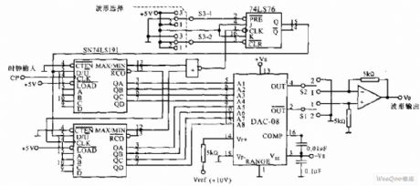
The multi-function numerical control waveform generator circuit is as shown in the figure, it is designed as one kind of digital waveform generator application circuit that can produce the triangular wave and the sawtooth waveform. In the figure, the 8-bit reversible counter is composed of two 4-bit reversible counter SN74L191, the increasing or decreasing count output is used as the input of D/A converter, the output voltage Vo is the gradually increasing or decreasing voltage, it changes linearly. When the manual switch S3 is in position 2 , the trigger's output Q=1, the counter counts diminishly, and it outputs the negative sawtooth wave; when the manual switch S3 is in position 3 , Q=0, it outputs the positive sawtooth wave.
(View)
View full Circuit Diagram | Comments | Reading(902)
Square wave clock circuit
Published:2011/6/25 5:34:00 Author:TaoXi | Keyword: Square wave, clock circuit
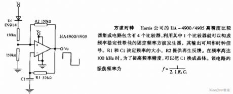
Square wave clock: The HA-4900/4905 high precision comparator integrated circuit which is produced by the Harris company has four comparators, you can form the fixed frequency square wave generator with good frequency stability by using only one comparator, the output can be used as the clock signal. The frequency is decided by the R1 and C1, R2 supplies the regeneration feedback. When the frequency is 100kHz, in order to improve the frequency precision, we can change C1 into the crystal. The oscillation frequency of this circuit f=1/2.1R1C1.
(View)
View full Circuit Diagram | Comments | Reading(590)
Adjustment application oscillator circuit
Published:2011/6/25 4:16:00 Author:TaoXi | Keyword: Adjustment application, oscillator circuit
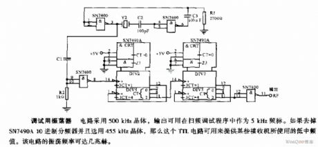
This circuit uses the 500kHz crystal, and its output can be used as the 5 kHz standard frequency in the frequency scanning debugging program. If you want to remove the SN7490A decimal divider and use the 455kHz crystal. so this TTL circuit can be used to supply the low frequency that are used by some receivers. The oscillation frequency of this circuit can be a few MHz.
(View)
View full Circuit Diagram | Comments | Reading(553)
Ultra low voltage white LED drive circuit
Published:2011/6/24 22:36:00 Author:TaoXi | Keyword: Ultra low voltage, white LED, drive circuit
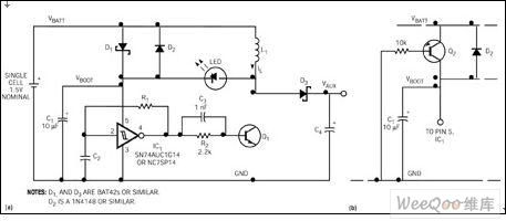
The positive voltage of the white LED is 3~5V, it is difficult that if we use only one battery to drive the white LED. This design uses the ultra-low operating voltage performance of the single-gate Schmitt inverter such as the 74HC14 or NC7SP14 (figure 1). When you add the battery power supply, the Schottky diode D1 conducts, the Schmitt trigger unsteady state multiple frequency oscillator starts working. The oscillation frequency depends on the timing components C2 and R1. When the output of IC1 is high level, the transistor Q1 conducts, the current of the inductor L1 increases gradually.
Figure 1 Ultra low voltage white LED drive circuit (View)
View full Circuit Diagram | Comments | Reading(515)
Automatic floodlight circuit with the two-way thyristor
Published:2011/6/24 23:32:00 Author:TaoXi | Keyword: Automatic floodlight, two-way thyristor

The circuit which uses the phototransistor as the illumination sensor is as shown in the figure. When the illumination is strong, the phototransistor and the L14C1 conduct. The diode VD3 conducts to make the voltage of capacitor C2 to zero, the two-way trigger tube VD5 and the two-way thyristor (triac) VT will not conduct, the light will not light. In the night, the L14C1 will not conduct, the voltage of C2 conducts the ST4 and VT, the light will turn on automaticly.
(View)
View full Circuit Diagram | Comments | Reading(526)
cinsisting of 555 single quantitative power supply controller circuit
Published:2011/6/20 8:57:00 Author:Fiona | Keyword: cinsisting of 555, single quantitative power supply controller

Load detection circuit is composed of the transformer B,D1,C1,W1 and it is used to measure circuit.Electronic switch is composed of the BG1,DW1 and R1 and it is controlled by testing signal.The regular time of the single stable circuit which is composed of the IC (555) and R3, C4 is td = 1.1R3C4,the parameters of the corresponding time is about four minutes. When the power exceeds the load,the voltage regulator tube DW1 is breakdown,BG1 saturated conducts,555 is set due to the potential of ② pin is low,the high level output by ③ pin makes the SCR conduct,relay J pulls in,contactor J1-1, J2-2 is off,cuts off ~ 220V power supply.
(View)
View full Circuit Diagram | Comments | Reading(539)
W140/W202 infrared remote control central door locking system components position circuit
Published:2011/6/13 9:47:00 Author:Christina | Keyword: infrared, remote control, central door locking system, components position

View full Circuit Diagram | Comments | Reading(3920)
consisting of 555 the indoor humidity control circuit
Published:2011/6/20 8:57:00 Author:Fiona | Keyword: consisting of 555, the indoor humidity control

The controller is composed of step-down rectifier circuit,humidity sensor,single stable circuit,Silicon controlled control circuit and so on.Step-down rectifier circuit provides DC voltage VDD=+10V for the whole control circuit.Single stable circuit is composed of IC,wet sensitive network,R5,C1 and so on. When the humidity exceeds the predetermined value,555 ② pin potential is high,555 is reset,the low level output by ③ pin makes the SCR conduct,turns on exhaust fan power To do exhaust to reduce humidity.Emission time is determined by timing time constant R5C1 and the level of control terminals ⑤ pin.Adjust W1 be preset the emission time.
(View)
View full Circuit Diagram | Comments | Reading(2459)
W129 infrared remote control central door locking system fault code circuit
Published:2011/6/13 9:48:00 Author:Christina | Keyword: infrared, remote control, central door locking system, fault code

View full Circuit Diagram | Comments | Reading(756)
consisiting of CH7555 program controller circuit
Published:2011/6/20 8:57:00 Author:Fiona | Keyword: consisiting of CH7555, program controller

Figure shows the program control circuit.The controller is composed of recycling program,power trigger circuit and so on. 4 pieces 555 circuit IC1 ~ IC4 are composed of different timing monostable circuit and series cycle trigger.Power trigger is composed of the IC7 (CD4069) hex inverter,so that all single-circuits are regular stable set.C6 (CC4081) is four 2-input AND gate;IC5 (CC4044) is the four R. S latch.When you press the start button,IC1 is set and enters single state temporary stability state.That is the first program to run.
(View)
View full Circuit Diagram | Comments | Reading(493)
Consisting of 555 water and sewage control circuit
Published:2011/6/18 8:01:00 Author:Fiona | Keyword: consisting of 555, water and sewage control

The controller consists of the step-down rectifier circuit,the water level probe (a, b, c),555 trigger,relay control circuit and so on.The step-down rectifier circuit provides DC voltage for the whole control circuit.When controller is used for water tower sheung shui,if the water level is below the point b,then 555 is set due to the ② pin potential is low level,the high level output by 3 pin makes the relay J close,contact J1-1 connects,pump starts to sheung shui. When the water level rises to a point,555 is set due to the ⑥ pin potential is higher than 2/3VDD,the low level output by 3 pin makes the relay J release,contact J1-1 is off,pump stops without electricity.So that the water level maintains a certain range.
(View)
View full Circuit Diagram | Comments | Reading(1373)
Mercedes-Benz connection LED lamp circuit
Published:2011/6/13 9:50:00 Author:Christina | Keyword: Mercedes-Benz, connection, LED lamp

The Mercedes-Benz connection LED lamp circuit
(View)
View full Circuit Diagram | Comments | Reading(721)
W129 infrared remote control (IR) central locking system (CLS) components position circuit
Published:2011/6/13 9:51:00 Author:Christina | Keyword: infrared, remote control, central locking system, components position, IR, CLS

View full Circuit Diagram | Comments | Reading(1052)
The protection circuit composed of the pressure sensitive resistor
Published:2011/6/13 20:12:00 Author:Christina | Keyword: protection circuit, pressure sensitive resistor

The pressure sensitive resistor is always connected with the input port of the protected electrical in the circuit, as the figure shows. From the figure we can see the voltage divider is composed of the pressure sensitive resistor's impedance zv and the circuit's total impedance, so the limit voltage of the pressure sensitive resistor can be determined by the formula: Vc=VsZv/(Zs+Zv)
VC--limit voltage;VS--surge voltage;ZV--the impedance of the pressure sensitive resistor;ZS--the total impedance of the circuit.
The formula shows that when the large current gets through the Zv, the transient overvoltage lands on it mostly, so the voltage of the protected electric equipment is lower than the limit voltage of it, so this circuit can play the protection function.
Figure The protection circuit composed of the pressure sensitive resistor (View)
View full Circuit Diagram | Comments | Reading(529)
H type of a brush type control circuit
Published:2011/6/20 9:13:00 Author:Fiona | Keyword: H type, a brush type control

MC33035 can use the least amount of devices to control a brushless motor by driving an H electricity four bridge.The key of this control is:To code the input sensor into 100, meanwhile,when the controller forward / reverse pin is logic level 1,it should also produce the drive signal of top to left Q1 and button to right Q3, and when the forward / reverse pin is logic level,it should also produce the drive signal of top to right Q4 and button to left Q2.The code ensures that H-drive meets the direction and speed control requirements. The controller can work properly in about 25kHz PWM frequency.
(View)
View full Circuit Diagram | Comments | Reading(1010)
The LED suggested circuit powered by ordinary AAA batteries
Published:2011/6/20 9:40:00 Author:Fiona | Keyword: The LED suggested, powered by ordinary AAA batteries


When the battery voltage is 4.38V,the measured current is about 150mA, LED's voltage drop is 3.2V. In order to effectively extend battery using time, the writer decides to cascade a small value of current limiting resistor behind the button switch K, after the repeated test,the current is 120mA when using 2.7Ω resistor,the brightness is no significant change. If it is too expensive,the circuit can use 220V AC power which requires a suitable power adapter,the writer suggests to choose the abandoned mobile home battery charger, because the mobile phone chargers plug have various different shape,it should be transformed by mono headphones plug in advance,output voltage of the charger which is found by the writer is 6.28V.
(View)
View full Circuit Diagram | Comments | Reading(909)
LED lights supplied power by telephone lines circuit
Published:2011/6/20 22:18:00 Author:Fiona | Keyword: LED lights, supplied power by telephone lines


Taking into account the LED lights of telephone lines exist a negative impact on the internet, so that it can't always be connected to the telephone line,the writer also has some transformation of the light,the circuit after transformation is shown in Figure 2,changes the middle of the 6 LED in parallel,while increases a 3.6V lithium-ion cell phone batteries,usually uses the built-in of new work lithium electricity,when the limiting resistance is 5.6Ω,the operating current is about 120mA, brightness is more satisfactory.It can still use insert telephone extension interface lighting in emergency,operating current after transformation is about 4.6mA, brightness is said to the past.
(View)
View full Circuit Diagram | Comments | Reading(1906)
LED emergency light charged by own lead acid battery circuit
Published:2011/6/20 22:44:00 Author:Fiona | Keyword: LED emergency light, charged by own lead acid battery
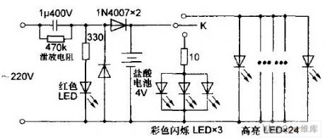
When the lead-acid battery voltage is 4V, the measured work current of the lights is about 60mA, bright LED current is more than 600 mA.So the big current makes lighting time after each full charge not be too long and damages the internal structure of the battery so that shorten the life,so it is necessary to string into a current-limiting resistance of small resistance with highlight LED.After numerous experiments, when selecting 1.2Ω,working current eventually drop to 320 mA, while the brightness change is not obvious,Because the lamp hasn't changed much, the circuit of after transformation is omitted.
(View)
View full Circuit Diagram | Comments | Reading(2408)
the op-amp analog switch with high anti-interference ability circuit
Published:2011/6/21 1:35:00 Author:Fiona | Keyword: the op-amp analog switch, high anti-interference ability

The circuit uses analog electronic switches to replace the node switch to prevent sparking and radio-frequency interference.The picture shows the circuit using junction field-effect transistor and operational amplifier and its equivalent mechanical lines.When the input signal UE (UE1, UE2) has control signal (high 10V) in the B side,the junction field-effect transistor conducts, produces the output signal UA through the operational amplifier. The picture is shown a similar circuit.
(View)
View full Circuit Diagram | Comments | Reading(1094)
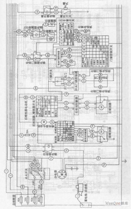
Jinbei RZH115LB a passenger vehicle circuit
Published:2011/6/24 10:34:00 Author:Fiona | Keyword: Jinbei RZH115LB, passenger vehicle
View full Circuit Diagram | Comments | Reading(471)
| Pages:1699/2234 At 2016811682168316841685168616871688168916901691169216931694169516961697169816991700Under 20 |
Circuit Categories
power supply circuit
Amplifier Circuit
Basic Circuit
LED and Light Circuit
Sensor Circuit
Signal Processing
Electrical Equipment Circuit
Control Circuit
Remote Control Circuit
A/D-D/A Converter Circuit
Audio Circuit
Measuring and Test Circuit
Communication Circuit
Computer-Related Circuit
555 Circuit
Automotive Circuit
Repairing Circuit