
Circuit Diagram
Index 1690
Mazda 94THUNDERB (3.8L, SC) transmission circuit
Published:2011/6/21 0:18:00 Author:John | Keyword: transmission

Mazda 94THUNDERB (3.8L, SC) transmission circuit is shown.
(View)
View full Circuit Diagram | Comments | Reading(617)
(CD4001) logical pen circuit with function of displaying the open circuit
Published:2011/6/17 6:53:00 Author:chopper | Keyword: logical pen, display the open circuit

View full Circuit Diagram | Comments | Reading(669)
Logarithmic characteristic photosensitive circuit
Published:2011/6/22 2:39:00 Author:TaoXi | Keyword: Logarithmic characteristic, photosensitive
Logarithmic characteristic photosensitive circuit (View)
View full Circuit Diagram | Comments | Reading(444)
CD060 nickel-cadmium battery charger circuit of timing function
Published:2011/6/17 6:51:00 Author:chopper | Keyword: nickel-cadmium battery, charger circuit, timing

This circuit is a timing charger,the charging time can be adjusted between 5h and 25h.If the power supply is cut during charging,this circuit can accumulate the total time.This circuit can charge the number 5 nickel cadmium battery. (View)
View full Circuit Diagram | Comments | Reading(1163)
Mazda 94THUNDERB shift interlock circuit
Published:2011/6/21 0:18:00 Author:John | Keyword: shift interlock

Mazda 94THUNDERB shift interlock circuit is shown.
(View)
View full Circuit Diagram | Comments | Reading(698)
Light isolation solid power relay circuit
Published:2011/6/22 2:52:00 Author:TaoXi | Keyword: Light isolation, solid, power relay
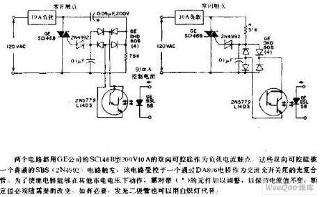
The two circuits use the SC146B type 200V, 10A bidirectional thyristor as the load current contact point which is produced by the GE company. The bidirectional thyristors are triggered by a normal SBS(2N4992) circuit. This circuit is controlled by a light composite tube which can be used as the AC light switch through the DA806 bridge. In order to make this relay to work in other city electricity voltage, we need to adjust the components with the * mark to maintain the current. The rated value needs to be changed according to the need. If necessary, we can use the incandescent lamp to replace the light-emitting diode.
(View)
View full Circuit Diagram | Comments | Reading(612)
Mazda 94THUNDERB (without DRL) headlamps and fog lamps circuit
Published:2011/6/21 0:17:00 Author:John | Keyword: headlamp, fog lamp

Mazda 94THUNDERB (without DRL) headlamps and fog lamps circuit is shown.
(View)
View full Circuit Diagram | Comments | Reading(552)
logical pen of Luminous display type circuit of NE555
Published:2011/6/17 6:46:00 Author:chopper | Keyword: Luminous display, logical pen circuit

View full Circuit Diagram | Comments | Reading(568)
Light interrupt detector circuit
Published:2011/6/22 3:12:00 Author:TaoXi | Keyword: Light interrupt, detector

When the light which projects on the light-excited SCR interrupts, the voltage of the single-pole switch 2N4990's anode tends to the forward direction in next positive half-cycle. When the voltage reaches to the open voltage of the unidirectional switch, it triggers the unidirectional switch and the SCR C230B. As long as the light does not shine on the light-excited SCR, the load will be stimulated.
(View)
View full Circuit Diagram | Comments | Reading(661)
Mazda 94THUNDERB cruise control circuit
Published:2011/6/21 0:17:00 Author:John | Keyword: cruise control

Mazda 94THUNDERB cruise control circuit is shown.
(View)
View full Circuit Diagram | Comments | Reading(608)
Mazda 94THUNDERB (4.6L) charging system circuit
Published:2011/6/21 0:17:00 Author:John | Keyword: charging system

Mazda 94THUNDERB (4.6L) charging system circuit is shown.
(View)
View full Circuit Diagram | Comments | Reading(672)
Mazda 94THUNDERB electric rear mirror circuit
Published:2011/6/21 0:17:00 Author:John | Keyword: electric rear mirror

Mazda 94THUNDERB electric rear mirror circuit is shown.
(View)
View full Circuit Diagram | Comments | Reading(639)
Mazda 94THUNDERB intermittent wiper cleaner circuit
Published:2011/6/21 0:17:00 Author:John | Keyword: intermittent wiper cleaner

Mazda 94THUNDERB intermittent wiper cleaner circuit is shown.
(View)
View full Circuit Diagram | Comments | Reading(887)
Mazda 94THUNDERB external light circuit
Published:2011/6/21 0:16:00 Author:John | Keyword: external light

Mazda 94THUNDERB external light circuit is shown.
(View)
View full Circuit Diagram | Comments | Reading(543)
Mazda 94THUNDERBIRD security circuit
Published:2011/6/21 0:16:00 Author:John

Mazda 94THUNDERBIRD security circuit is shown.
(View)
View full Circuit Diagram | Comments | Reading(534)
Adjustable light detection switch circuit
Published:2011/6/22 3:38:00 Author:TaoXi | Keyword: Adjustable light, detection, switch circuit

The R2 can be used to set the threshold value of the circuit. When the light intensity of the PC1 surface reduces, the resistance (a tin sulfide light resistance) of PC1 increases. This makes the voltage of 741 reverse phase input port to reduce. When you use the R2 to adjust the reference voltage of 741 in-phase port, as long as the PC1 has no light, the comparator will has the low level, this conducts Q1 and makes the relay K1 to act.
(View)
View full Circuit Diagram | Comments | Reading(652)
Mazda 94THUNDERBIRD Ground distribution circuit
Published:2011/6/21 0:15:00 Author:John | Keyword: Ground distribution

Mazda 94THUNDERBIRD Ground distribution circuit is shown.
(View)
View full Circuit Diagram | Comments | Reading(564)
The stable-amplitude and low-distortion power signal generator of XG404C
Published:2011/6/13 23:59:00 Author:Borg | Keyword: stable-amplitude, low-distortion, power signal generator
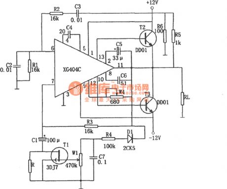
In the figure is a stable-amplitude and low-distortion power signal generator of XG404C. The circuit is a good power signal source which consists of the audio power amplifier XG404. In the figure, C2, R1,C3 and R2 form a Wien-bridge frequency-selecting net, which decides the frequency of the sine wave. The leakage equivalent resistors of R3, R and FET pipe T1 determine the magnified times of the amplifier non-inverting input. When R=R1=R2 and C=C2=C3, the oscillating frequency of the circuit is f0=1/2πRC , according to the element value, the frequency is about 1kHz. (View)
View full Circuit Diagram | Comments | Reading(1391)
Double color complementation alternate display running water color light circuit
Published:2011/6/22 19:39:00 Author:TaoXi | Keyword: Double color, complementation, alternate display, running water, color light
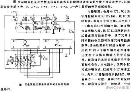
The circuit principle: in the circuit, IC1 and IC2 are the color light control special IC RY168. This IC is in the soft package, it has eight pinouts. The 2-5 pins are the color light control output port, the pin-8 is the audio input port. This IC uses the dual-channel leap mode to output the color light control signal, you can change the internal oscillation frequency by adjusting the potentiometer which is connected with the pin-6, then you can change the chase rate of the color light. In addition, the chase rate of the four output ports of this IC is controlled by the music signal which is input from pin-8. In this circuit, there are two ICs connected into parallel.
(View)
View full Circuit Diagram | Comments | Reading(462)
The oscillating circuit with the output of triangular waves and square waves (LM107、LM101A)
Published:2011/6/14 1:07:00 Author:Borg | Keyword: oscillating circuit, triangular waves, square waves
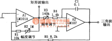
In the figure is the oscillating circuit with the output of triangular waves and square waves. This circuit consists of a Miller integrator A2 and Schmidt trigger A1, which can output triangular and square waves. The oscillating frequency is decided by the time constant of Miller integrator (R3+R4)*C1 and the lag voltage of the trigger Vcc(R1+R2)/(R1+R2+R3), of which Vcc is the power supply voltage. By adjusting the resistor R3, the oscillating frequency is also changed, and by adjusting resistor R2, either the output amplitude of the triangular wave or the oscillating frequency can be changed. A2 outputs the triangular wave and A1 outputs the square wave. (View)
View full Circuit Diagram | Comments | Reading(435)
| Pages:1690/2234 At 2016811682168316841685168616871688168916901691169216931694169516961697169816991700Under 20 |
Circuit Categories
power supply circuit
Amplifier Circuit
Basic Circuit
LED and Light Circuit
Sensor Circuit
Signal Processing
Electrical Equipment Circuit
Control Circuit
Remote Control Circuit
A/D-D/A Converter Circuit
Audio Circuit
Measuring and Test Circuit
Communication Circuit
Computer-Related Circuit
555 Circuit
Automotive Circuit
Repairing Circuit