Automotive Circuit
The oscillating circuit with the output of triangular waves and square waves (LM107、LM101A)
Published:2011/6/14 1:07:00 Author:Borg | Keyword: oscillating circuit, triangular waves, square waves | From:SeekIC
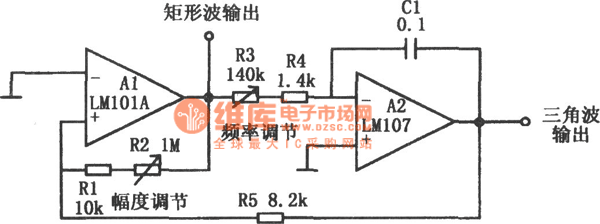
In the figure is the oscillating circuit with the output of triangular waves and square waves. This circuit consists of a Miller integrator A2 and Schmidt trigger A1, which can output triangular and square waves. The oscillating frequency is decided by the time constant of Miller integrator (R3+R4)*C1 and the lag voltage of the trigger Vcc(R1+R2)/(R1+R2+R3), of which Vcc is the power supply voltage. By adjusting the resistor R3, the oscillating frequency is also changed, and by adjusting resistor R2, either the output amplitude of the triangular wave or the oscillating frequency can be changed. A2 outputs the triangular wave and A1 outputs the square wave.
Reprinted Url Of This Article:
http://www.seekic.com/circuit_diagram/Automotive_Circuit/The_oscillating_circuit_with_the_output_of_triangular_waves_and_square_waves_LM107-LM101A.html
Print this Page | Comments | Reading(3)

Article Categories
power supply circuit
Amplifier Circuit
Basic Circuit
LED and Light Circuit
Sensor Circuit
Signal Processing
Electrical Equipment Circuit
Control Circuit
Remote Control Circuit
A/D-D/A Converter Circuit
Audio Circuit
Measuring and Test Circuit
Communication Circuit
Computer-Related Circuit
555 Circuit
Automotive Circuit
Repairing Circuit
Code: