
Circuit Diagram
Index 1696
principle of Glanz microwave oven circuit
Published:2011/6/22 19:55:00 Author:chopper | Keyword: principle, Glanz, microwave oven

View full Circuit Diagram | Comments | Reading(2036)
capacitive step-down driving LED circuit
Published:2011/6/22 19:59:00 Author:chopper | Keyword: capacitive, step-down, LED, driving

View full Circuit Diagram | Comments | Reading(603)
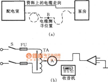
subterranean cable detection circuit with radio
Published:2011/6/22 20:02:00 Author:chopper | Keyword: subterranean cable, detection circuit, radio
View full Circuit Diagram | Comments | Reading(463)
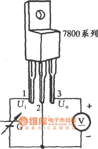
work performance test circuit of three-terminal integrated regulator circuit
Published:2011/6/22 20:48:00 Author:chopper | Keyword: work performance, test circuit, three-terminal, integrated regulator circuit
View full Circuit Diagram | Comments | Reading(300)
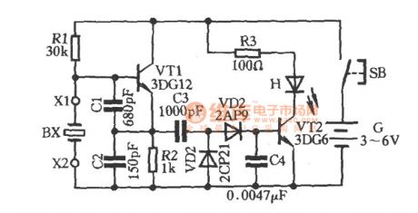
quartz crystal pick circuit
Published:2011/6/22 20:50:00 Author:chopper | Keyword: quartz crystal, pick circuit
View full Circuit Diagram | Comments | Reading(352)
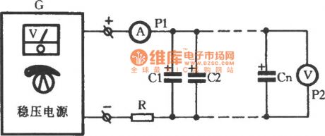
aluminium electrolytic capacitor conditioning circuit
Published:2011/6/22 20:55:00 Author:chopper | Keyword: aluminium electrolytic capacitor, conditioning circuit
View full Circuit Diagram | Comments | Reading(435)
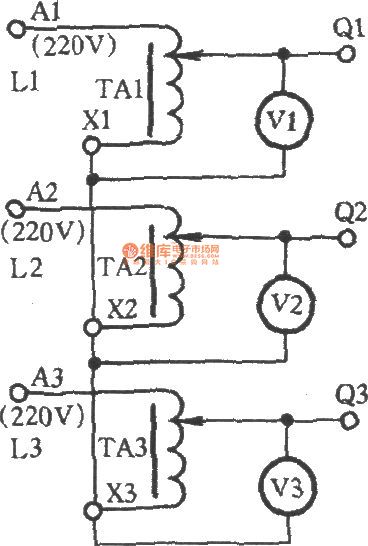
gaining 0-433V voltage by star-star connection of 3 boosters
Published:2011/6/22 21:00:00 Author:chopper | Keyword: 0-433V voltage, star-star connection, 3 boosters
View full Circuit Diagram | Comments | Reading(389)
0.1C5A standard nickel-cadmium battery charger circuit of CD4541
Published:2011/6/20 6:09:00 Author:chopper | Keyword: 0.1C5A, standard nickel-cadmium battery, charger circuit

The following circuit makes use of the constant-current characteristic of capacitor and adopts pulsant direct current source to charge.Its effect is greater than pure DC,and it can charge one or more nickel-cadmium batteries.
(View)
View full Circuit Diagram | Comments | Reading(4402)
power follower of CW117/CW217/CW317 circuit
Published:2011/6/16 0:48:00 Author:chopper | Keyword: power follower

View full Circuit Diagram | Comments | Reading(1189)
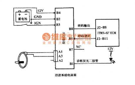
automobile burglary-resisting system circuit
Published:2011/6/14 8:27:00 Author:chopper | Keyword: automobile, burglary-resisting system
View full Circuit Diagram | Comments | Reading(450)
TAl226NA transient state of luminance improvement integrated circuit
Published:2011/6/16 22:14:00 Author:chopper | Keyword: transient state, luminance, improvement, integrated circuit

TAl226NA is a transient state of luminance improvement integrated circuit,and it is applied to various large-screen colour TVs to improve the transient state of luminance.Its function and data of pins of the integrated circuit are shown as chart 1.
(View)
View full Circuit Diagram | Comments | Reading(468)
CW200 charger cirucit
Published:2011/6/16 22:07:00 Author:chopper | Keyword: charger

View full Circuit Diagram | Comments | Reading(704)
TTL integrated door circuit
Published:2011/6/16 1:10:00 Author:chopper | Keyword: TTL, integrated door

View full Circuit Diagram | Comments | Reading(497)
The emitter circuit composed of BA1404
Published:2011/6/25 20:43:00 Author:qqtang | Keyword: emitter circuit
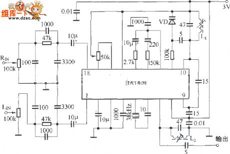
BA1404 is the special integrated circuit of FM stereo sound, as the working feature is good, it is also used in wireless control. BA1404 needs a low power supply voltage, its power is also low, and its structure is completed, it needs a few external elements, and finally, it works stably and reliably. The notes of using BA1404 are listed as follows: (1) to keep the frequency feature of the emitter conforming to that of the FM broadcast receiver, we need to fix a pre-emphasizer whose time constant is 50μs in the left and right channel, see as the figure.
Figure: The emitter circuit composed of BA1404 (View)
View full Circuit Diagram | Comments | Reading(2311)
The TS26 principle circuit
Published:2011/6/25 20:30:00 Author:qqtang
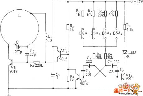
Figure: The TS26 principle circuit (View)
View full Circuit Diagram | Comments | Reading(404)
The ±5~25V dual polarity regulated power supply circuit
Published:2011/6/25 20:29:00 Author:qqtang | Keyword: dual polarity, power supply

View full Circuit Diagram | Comments | Reading(775)
The μPC1373H/HA typical application circuit
Published:2011/6/25 20:28:00 Author:qqtang
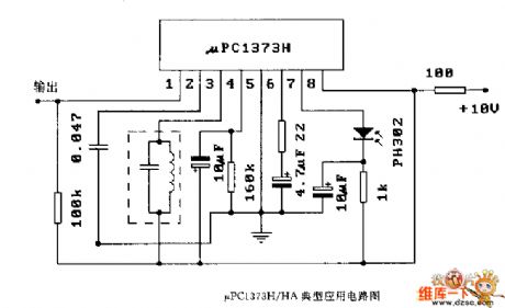
Figure: The μPC1373H/HA typical application circuit (View)
View full Circuit Diagram | Comments | Reading(376)
The YN9101 logic frame circuit
Published:2011/6/25 20:26:00 Author:qqtang | Keyword: logic frame
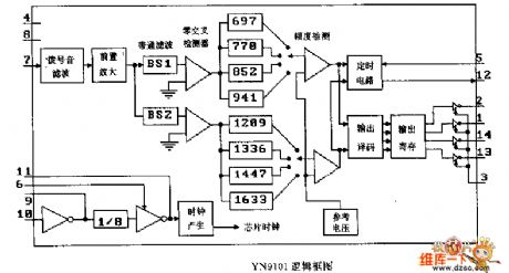
Figure: The YN9101 logic frame circuit (View)
View full Circuit Diagram | Comments | Reading(425)
The FET pipe drive timing flash circuit
Published:2011/6/25 20:25:00 Author:qqtang | Keyword: FET pipe, timing flash circuit

With the figured circuit, we can compose a circle light timing control circuit with a few elements. The circuit consists of the MOS time-base circuit 7555, CMOS decimal counter(pulse distributor) 4017 and end stage VMOS power transistor. The power transistor controls the bulb whose maximum current is 2A. The resistor RV between the bulb and the power supply +UH is used to limit the connected current.
The time-base frequency is adjusted by the potentiometer (about 0.5~10HZ). The 9 stage circling storage is controlled by the square wave output signal with the help of the clock. (View)
View full Circuit Diagram | Comments | Reading(536)
Ten-Channel Temperature Patrol Detecting Circuit Diagram
Published:2011/6/26 1:03:00 Author:Vicky | Keyword: Ten-Channel Temperature Patrol Detecting

Temperature Sensor adopts 3AX31 and is in the form of diode. When the temperature changes, the resistance K presents linear variation.
Oscillator is composed of IC1 (555), rce, R1, and C1 etc. The frequency is: f=1.44/(R1+2rce)C1. Therefore, the rce presents linear variation with the changing of temperature, and f also varies proportionally to realize the conversion of temperature and frequency. If ten spots are to be tested, then 10 temperature-frequency converters are needed.
In the circuit, IC2 adopts hex inverter CD4069, and F1,F2,F3 make up trigger generator of 0.2 Hz, that is to send a count pulse CP to the count circuit IC3 every 5 seconds. (View)
View full Circuit Diagram | Comments | Reading(523)
| Pages:1696/2234 At 2016811682168316841685168616871688168916901691169216931694169516961697169816991700Under 20 |
Circuit Categories
power supply circuit
Amplifier Circuit
Basic Circuit
LED and Light Circuit
Sensor Circuit
Signal Processing
Electrical Equipment Circuit
Control Circuit
Remote Control Circuit
A/D-D/A Converter Circuit
Audio Circuit
Measuring and Test Circuit
Communication Circuit
Computer-Related Circuit
555 Circuit
Automotive Circuit
Repairing Circuit