power supply circuit
Large current adjustable voltage stabilization power supply circuit
Published:2011/6/22 1:48:00 Author:TaoXi | Keyword: Large current, adjustable, voltage stabilization, power supply | From:SeekIC
Circuit and working principle
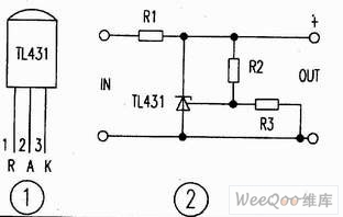
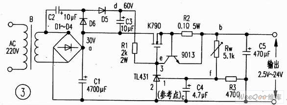
The pin figure of the TL413 is as shown in figure 1, the typical application of the TL413 is as shown in figure 2, the output voltage of pin-2 and pin-3 are V=2.5(R2十R3)V/R3. If we change the resistance value of R2, we can change the output reference voltage. Figure 3 shows the output current (about 6A) that is composed of the voltage reference and the regulator (the TL413 drives the external FET K790), this circuit is simple and safe.
The voltage regulation process: when the output voltage reduces, the electric potential of point f reduces, this potential is amplified by the T1431 to increase the voltage of point e, and it is adjusted by the K790, the electric potential of point b rises; on the contrary, when the output voltage rises, the electric potential of point f rises too, the electric potential of point e reduces, and it is adjusted by the K790, the electric potential of point b reduces.
Reprinted Url Of This Article:
http://www.seekic.com/circuit_diagram/Power_Supply_Circuit/Large_current_adjustable_voltage_stabilization_power_supply_circuit.html
Print this Page | Comments | Reading(3)

Article Categories
power supply circuit
Amplifier Circuit
Basic Circuit
LED and Light Circuit
Sensor Circuit
Signal Processing
Electrical Equipment Circuit
Control Circuit
Remote Control Circuit
A/D-D/A Converter Circuit
Audio Circuit
Measuring and Test Circuit
Communication Circuit
Computer-Related Circuit
555 Circuit
Automotive Circuit
Repairing Circuit
Code: