Control Circuit
Ten hours delay circuit
Published:2011/6/20 3:50:00 Author:TaoXi | Keyword: Ten hours, delay circuit | From:SeekIC

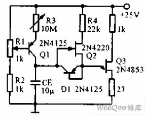
The ten hours delay circuit is as shown in the figure. The constant current source is composed of the transistor Q1 and the R1, R2, R3, the charge current can be adjusted to a few nA. The source follower is composed of Q2, the output is connected with the emitter of the single junction transistor Q3. The transistor which is connected into the diode supplies the low resistance discharging pathway to the timing capacitance. The delay time linearly changes with R3.
Reprinted Url Of This Article:
http://www.seekic.com/circuit_diagram/Control_Circuit/Ten_hours_delay_circuit.html
Print this Page | Comments | Reading(3)

Article Categories
power supply circuit
Amplifier Circuit
Basic Circuit
LED and Light Circuit
Sensor Circuit
Signal Processing
Electrical Equipment Circuit
Control Circuit
Remote Control Circuit
A/D-D/A Converter Circuit
Audio Circuit
Measuring and Test Circuit
Communication Circuit
Computer-Related Circuit
555 Circuit
Automotive Circuit
Repairing Circuit
Code: