
Circuit Diagram
Index 92
PIC 16F628 MiniDCC© Controller Circuit Schematic
Published:2013/6/21 2:46:00 Author:muriel | Keyword: PIC 16F628, MiniDCC© , Controller Circuit Schematic

View full Circuit Diagram | Comments | Reading(1248)
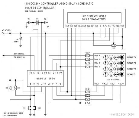
PIC 16C84 MiniDCC© Controller Circuit Schematic
Published:2013/6/21 2:46:00 Author:muriel | Keyword: PIC 16C84, MiniDCC©, Controller Circuit Schematic
View full Circuit Diagram | Comments | Reading(843)
The 3 Amp Booster For My MiniDCC© System
Published:2013/6/21 2:45:00 Author:muriel | Keyword: 3 Amp, Booster, MiniDCC© System
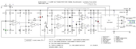
The following schematic is for the booster that was built for my MiniDCC® System. Designed around an LMD 18200 H-Bridge. The circuit includes signal failure detector and over current protection that will remove power to the tracks should either activate.
The signal detector will automatically clear itself but the over-current detector must be manually reset.
(View)
View full Circuit Diagram | Comments | Reading(789)
Zero Stretching Of DCC Voltages
Published:2013/6/21 2:44:00 Author:muriel | Keyword: Zero Stretching , DCC Voltages
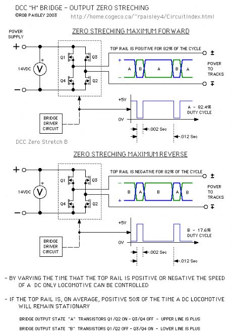
The next diagram shows a very simplistic explanation to Zero Stretching as it applies to DCC systems.
As in the above diagrams the rate at which the voltage changes polarities has not been considered. The important factor in Zero Stretching is the average time that the voltage to the track is either positive or negative.
(View)
View full Circuit Diagram | Comments | Reading(583)
Full Wave Rectification
Published:2013/6/21 2:42:00 Author:muriel | Keyword: Full Wave Rectification
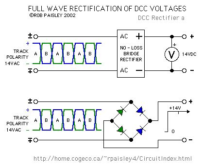
The next diagram shows the effect of rectifying a DCC voltage with a full wave bridge. The voltage at the output of the bridge is equal to the input minus the drop across the diodes.
The small tick in the output of the bridge occurs when the polarity of the H-Bridge reverses. The size of the ticks is largely determined by the efficiencies of the H-Bridge and rectifier bridge and in most cases can be ignored. This is why filter capacitors are not needed for decoders.Diodes used to rectify DCC should be Schottky or high speed silicon types. Diodes of the 1N4000 and 1N5400 series are not suitable for this application due to their slow turn-off times. (View)
View full Circuit Diagram | Comments | Reading(665)
Basic Half Wave - DCC H-Bridge Circuit
Published:2013/6/21 2:41:00 Author:muriel | Keyword: Basic Half Wave , DCC H-Bridge Circuit
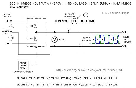
The next schematic shows a Half DCC H-Bridge circuit in a very basic form. The reversing switch has now been replaced by two transistors that are alternately switched ON and OFF.
Oscilloscopes A and B are not relevant to this circuit as the output of the bridge is actually referenced to the common of the power supply.
The waveform for the C oscilloscope above does apply to this circuit and illustrates why a 28 volt signal appears at the output while the instantaneous voltage does not exceed one half of the maximum supply voltage.
(View)
View full Circuit Diagram | Comments | Reading(1189)
Basic DCC Full H-Bridge Circuit
Published:2013/6/21 2:41:00 Author:muriel | Keyword: Basic DCC Full H-Bridge Circuit
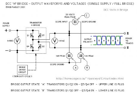
The next schematic shows a Full Wave - DCC H-Bridge circuit in a very basic form. The DPDT reversing switch has been replaced by four transistors connected in pairs that are alternately switched ON and OFF.
Oscilloscopes have been added to the circuit in order to show what the waveforms would look like at various points in the system. Illustrations explaining the waveforms follow this diagram. (View)
View full Circuit Diagram | Comments | Reading(832)
DCC Bridge Mimic Circuits
Published:2013/6/21 2:41:00 Author:muriel | Keyword: DCC Bridge Mimic Circuits
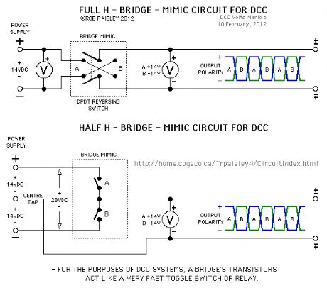
The first diagram illustrates the basic function of full and half H-Bridge circuits as used for model railroad DCC booster systems. (View)
View full Circuit Diagram | Comments | Reading(738)
Low Tech Meters For DCC Systems
Published:2013/6/21 2:40:00 Author:muriel | Keyword: Low Tech Meters, DCC Systems
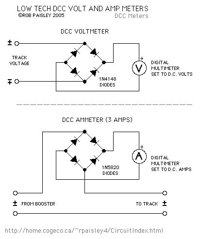
These are inexpensive low tech methods for measuring voltages and currents in DCC track systems. They are not as accurate as a high frequency AC volt and amp meters but if you only need an approximate indication these circuits will do the job.
The 1N5819 and 1N5820 diodes used here are Schottky types. This type of diode have a lower forward voltage drop (0.3V vs. 0.7V) than typical silicon diodes such as the 1N4000 series and can operate at efficiently at high frequencies.
(View)
View full Circuit Diagram | Comments | Reading(1111)
Meter Placement Diagram
Published:2013/6/21 2:39:00 Author:muriel | Keyword: Meter Placement Diagram
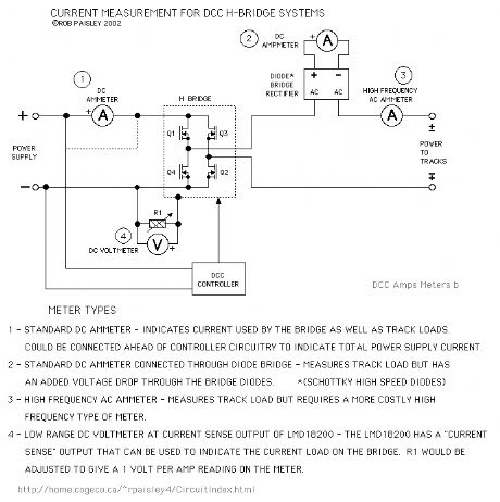
The following diagram shows a very simple schematic of an H-Bridge circuit with current indicating meters placed at various locations.
Text on the diagram indicates the type of meter and any special considerations involved. (View)
View full Circuit Diagram | Comments | Reading(617)
6 Aspect - Searchlight Signal With Simple Funtions
Published:2013/6/21 2:38:00 Author:muriel | Keyword: 6 Aspect, Searchlight Signal, Simple Funtions
The diagram shows the same circuit but with comparator inputs in place of the switches. This circuit provides the basic functions as the Simple Signals circuits that appear on this site. The Flash function is not yet implemented.
Two outputs have been added to the circuit that could be used as part of the Flash logic. These are the YELLOW INDICATION and RED INDICATION .
Approach lighting is the default for this circuit and is disabled by grounding the 'Approach Input' terminal.
The Flash funtion is activated by grounding the 'Flash Input' terminal.
(View)
View full Circuit Diagram | Comments | Reading(791)
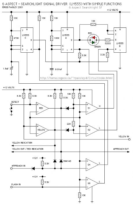
6 Aspect - Searchlight Signal Driver (LM555)
Published:2013/6/18 21:40:00 Author:muriel | Keyword: 6 Aspect, Searchlight Signal Driver , LM555

The circuit on this page is a 6 Aspect driver for a bicolour LED type Searchlight Signal. The available signal indications are; SOLID - RED, YELLOW, GREEN, and FLASHING - RED, YELLOW and GREEN. The circuit can also turn the signal OFF for approach lighting if desired.
As this is a driver circuit, there is no actual input logic to select the signal indication. This will be added when it has been worked out.
If you have any ideas on how such a logic system might function might work, please send an email with any details.
The first circuit on this page is controlled by four toggle switches. Refer to the tables on the diagram for switch positions and the resulting signal indications. (View)
View full Circuit Diagram | Comments | Reading(860)
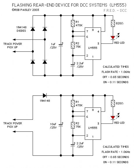
Flashing Rear-End Device For DCC
Published:2013/6/18 21:39:00 Author:muriel | Keyword: Flashing, Rear-End Device, DCC
View full Circuit Diagram | Comments | Reading(830)
Controlling Single Coil Switch Machines 4
Published:2013/6/18 21:38:00 Author:muriel | Keyword: Single Coil, Switch Machines
View full Circuit Diagram | Comments | Reading(642)
Controlling Single Coil Switch Machines 3
Published:2013/6/18 21:38:00 Author:muriel | Keyword: Single Coil, Switch Machines

View full Circuit Diagram | Comments | Reading(546)
Controlling Single Coil Switch Machines 2
Published:2013/6/18 21:37:00 Author:muriel | Keyword: Single Coil, Switch Machines

View full Circuit Diagram | Comments | Reading(568)
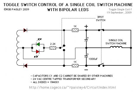
Controlling Single Coil Switch Machines
Published:2013/6/18 21:11:00 Author:muriel | Keyword: Controlling , Single Coil, Switch Machines

This circuit allow an ON-ON type DPDT toggle switch to control a single coil switch machine motor such as those made by Kato®. The handle of switch can then be used to indicate the route selected. The circuit is also able to control LEDs that could be used to indicate the selected route.
The main disadvantage of this circuit is the cost of two large electrolytic capacitors per switch machine. This could be offset by bulk or surplus purchases of the capacitors.
The size of the capacitors depends on the power needed to throw the turnout and the supply voltage. The value of the charging resistors depends on how quickly the turnout will be returned to its last position. A resistance of 1000 ohms would be a practical value in most cases.
NOTE:Although these circuits are show using DPDT toggle switches, 3 and 4 pole switches could also be used to control frog polarity or signals with the extra poles.
The resistors should have a 1/2 watt or greater power rating. The capacitors can be between 1,000 and 2,200 microfarads and should have a 35 volt or higher rating.
(View)
View full Circuit Diagram | Comments | Reading(846)
Set Signal / Then Throw
Published:2013/6/18 21:10:00 Author:muriel | Keyword: Set Signal , Then Throw

View full Circuit Diagram | Comments | Reading(533)
Fast Recovery Circuit
Published:2013/6/18 21:10:00 Author:muriel | Keyword: Fast Recovery Circuit

View full Circuit Diagram | Comments | Reading(497)
Separate Coils With Separate LED Control
Published:2013/6/18 21:09:00 Author:muriel | Keyword: Separate Coils , Separate LED Control


View full Circuit Diagram | Comments | Reading(667)
| Pages:92/2234 At 2081828384858687888990919293949596979899100Under 20 |
Circuit Categories
power supply circuit
Amplifier Circuit
Basic Circuit
LED and Light Circuit
Sensor Circuit
Signal Processing
Electrical Equipment Circuit
Control Circuit
Remote Control Circuit
A/D-D/A Converter Circuit
Audio Circuit
Measuring and Test Circuit
Communication Circuit
Computer-Related Circuit
555 Circuit
Automotive Circuit
Repairing Circuit