
Circuit Diagram
Index 100
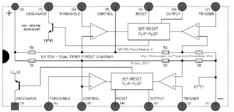
LM556- dual timer pinput diagram
Published:2013/6/6 20:43:00 Author:muriel | Keyword: LM556, dual timer, pinput diagram
View full Circuit Diagram | Comments | Reading(1134)
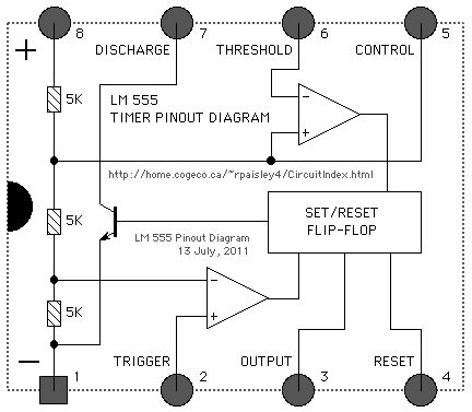
LM555 timer pinput diagram
Published:2013/6/6 20:42:00 Author:muriel | Keyword: LM555, timer pinput diagram
View full Circuit Diagram | Comments | Reading(934)
Twin Coil Switch Machine With Latching Relay
Published:2013/6/6 20:40:00 Author:muriel | Keyword: Twin Coil, Switch Machine , Latching Relay
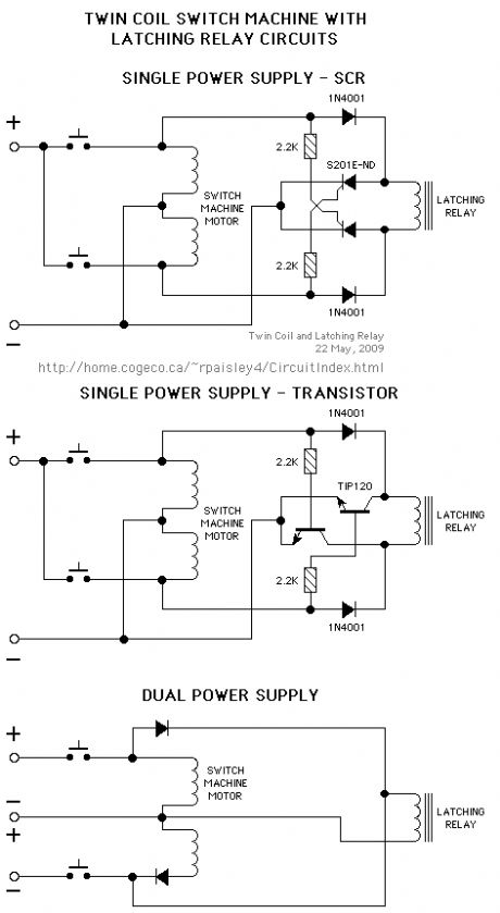
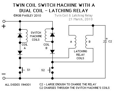
The schematics show how 'latching' type relays could be used with twin coil switch machines.
The SCR circuit may be the better choice for CD type power supplies as the SCR's don't need any gate current once they are switched ON.
(View)
View full Circuit Diagram | Comments | Reading(5886)
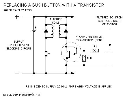
Transistor Control Of Switch Machines
Published:2013/6/6 20:39:00 Author:muriel | Keyword: Transistor Control , Switch Machines
View full Circuit Diagram | Comments | Reading(709)
A Power Supply For Use With Transistors
Published:2013/6/6 20:38:00 Author:muriel | Keyword: Power Supply , Transistors

The circuit is a variation of the SCR compatible power supply. This version can be used if transistors were used to control switch machines.
The only significant differences between this and the SCR compatible circuit is the removal of the time delay before recharging begins and the higher control current that would be required for transistors as opposed to silicon controlled rectifiers.
As with the SCR compatible circuit this version cannot be used with pushbuttons in the coil circuit as the charging current would not be cutoff when the button is pushed. (View)
View full Circuit Diagram | Comments | Reading(1127)
A Power Supply For Use With Silicon Controlled Rectifiers
Published:2013/6/6 20:37:00 Author:muriel | Keyword: Power Supply , Silicon Controlled Rectifiers
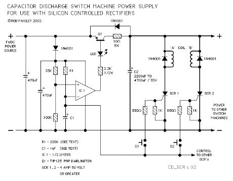
The next power supply is designed specifically for use with silicon controlled rectifiers. The SCR's would take the place of push buttons in the high current paths of the switch machine control circuits.
These devices are ideally suited for use where large current surges are expected and in many cases they are less expensive than darlington transistors. (View)
View full Circuit Diagram | Comments | Reading(1534)
Split Supply - Current Blocking Switch Machine Power Supply
Published:2013/6/6 20:37:00 Author:muriel | Keyword: Split Supply , Current Blocking , Switch Machine , Power Supply
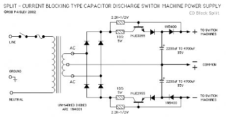
The next circuit is essentially the same as the one above except that a split of dual output is provided. The circuit therefore has a PLUS, MINUS and NEUTRAL output terminal but functions in the same manner as the single sided power supply circuit.
A 1N4001 diode has been placed in the emitter circuit of the power transistors to ensure that the proper voltage differential is achieved between the base and emitter junctions of these transistors.
This circuit has not been tested on a layout but should work as designed. Please take some time to experiment before actually installing the circuit. (View)
View full Circuit Diagram | Comments | Reading(1497)
Current Blocking Switch Machine Power Supply
Published:2013/6/6 20:36:00 Author:muriel | Keyword: Current Blocking , Switch Machine, Power Supply
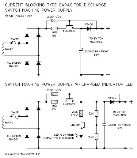
The Current Blocking type of switch machine supply is a widely used device and is well documented. It is reliable and practical design.
Simply stated; This type of supply blocks the charging current to the storage capacitor anytime current is flowing from the output of the circuit, such as when a switch machine is activated.
The only modification that this circuit might use is: (1) A resistor to limit the maximum charging current to a reasonable level. (2) a Capacitor Charged indicator. These additions are shown on the next diagram.
The first schematic on the following diagram shows a current blocking switch machine power supply with a 10 ohm resistor in the collector circuit of the blocking transistor. This resistor should be a wire wound type power resistor as it will have to handle peak currents of approximately 2.4 amps.
The second schematic shows a Capacitor Charged indicator added to the circuit. The LED will begin to glow when the voltage across the capacitor is approximately 16 volts and be fully lit at about 20 volts. (View)
View full Circuit Diagram | Comments | Reading(1172)
Simple But Effective Switch Machine Power Supply
Published:2013/6/6 20:35:00 Author:muriel | Keyword: Simple , Effective, Switch Machine, Power Supply
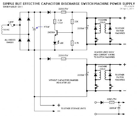
The first circuit of this page is for a classic Resistor / Capacitor unit but with a few modifications made.
The standard bugaboo with this type of circuit is the relatively long charging time of the capacitor. But if you are willing to wait the 1 second that a 2200uF capacitor takes to charge to 90 percent of its maximum voltage when a 220 ohm resistor is used this can be a simple and cost effective power supply. Using a lower resistance charging will shorten the charging time proportionally.
Shown in the top power supply circuit is an indicator circuit that shows when the capacitor is near its full charge. This is an optional feature and can be left out as shown on the second unit.
To increase the availability of switch machine power more than one discharge unit can be connected to a central transformer and rectifier / filter capacitor. This would allow smaller discharge units to be placed around the layout and used to operate machines that are nearby.
The diode in front of the 220 ohm resistor will prevent units from draining the voltage from each other when turnouts are thrown. Although this is unlikely to happen with an adequately sized supply transformer.
If the recharging time is not too important such as for machines that are not thrown often, the value or the 220 ohm resistor could be increased and its wattage reduced. The maximum potential load on the circuit will be reduced accordingly. If not as much pulse current is needed to throw the turnouts then the value of the capacitor could also be reduced.
With a 16 volt AC supply transformer the DC voltage across the capacitor will be about 21 volts and the maximum charging current will be 0.2 amps.
For a circuit of this type the charging time is dependent on the values of the resistor and capacitor used. For example if a 220 ohm resistor and a 2,200 microfarad capacitor are used then the charging time constant would be as follows.
220 Ohms X 2,200uf = 0.484 Seconds (1 Time Constant)
This is the time that the capacitor would take to reach 63 percent of the supply voltage. The time needed to reach approximately 88 percent of the supply voltage is 2 time constants.
2 X 0.484 = 0.986 Seconds (2 Time Constants)
For practical purposes the time to reach the supply voltage is 5 time constants.
If you have a little patience, about one second's worth, the basic resistor / capacitor power supply can be a very effective and economical system. However if you have the need for speed then one of the more sophisticated supplies is required. (View)
View full Circuit Diagram | Comments | Reading(1099)
Basic Twin Coil Switch Machine Power Supplies
Published:2013/6/6 20:35:00 Author:muriel | Keyword: Basic Twin Coil, Switch Machine, Power Supplies
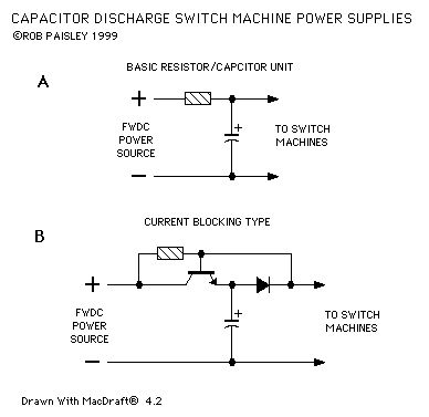
The following diagram shows two basic twin coil switch machine power supplies.
Circuit A is the simplest type but suffers from a relatively slow recovery rate.
Circuit B is a very popular power supply as it has a very good recovery time. This circuit has a high current surge when the capacitor is charging. (View)
View full Circuit Diagram | Comments | Reading(1127)
Multiple Sensors
Published:2013/6/6 20:33:00 Author:muriel | Keyword: Multiple Sensors
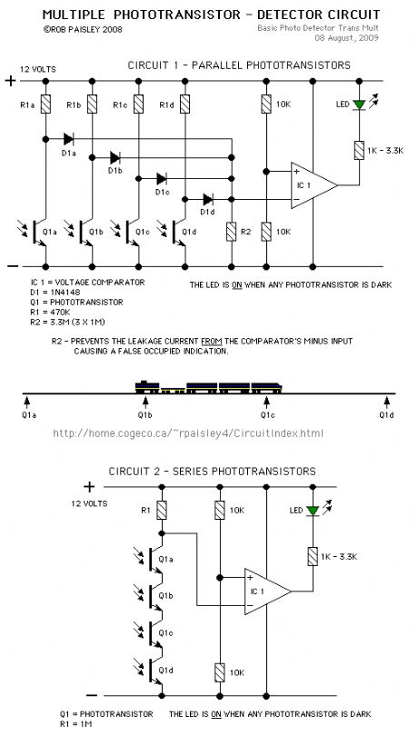
More than one phototransitor can be connected to a single voltage comparator. This would allow transistors to be placed along a section of track to indicate when a train is anywhere in that section.
As long as the train is long enough to cover two sensors the circuit will continuously detect the train.
(View)
View full Circuit Diagram | Comments | Reading(1331)
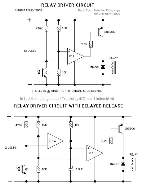
Phototransistor Detector Relay Driver
Published:2013/6/6 20:33:00 Author:muriel | Keyword: Phototransistor Detector, Relay Driver
View full Circuit Diagram | Comments | Reading(1520)
Practical Quad Photo-Detector Circuit
Published:2013/6/6 20:32:00 Author:muriel | Keyword: Practical Quad Photo-Detector Circuit

The next circuit is for a practical 4 photo-detector circuit using an LM339 Quad comparator IC. Although phototransistors are shown, photocells could also be used with the corresponding change in values for resistors R1 through R4.
This circuit can also be used for infrared detector circuits as shown above.
The values for resistors R7 through R10 can also be changed depending on the required LED current. (View)
View full Circuit Diagram | Comments | Reading(1229)
Infrared Light Photo-Detector Circuit
Published:2013/6/6 20:31:00 Author:muriel | Keyword: Infrared Light , Photo-Detector Circuit
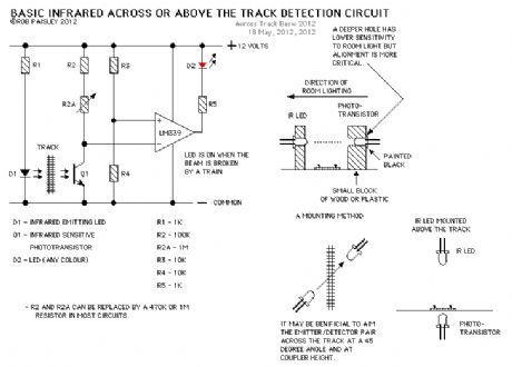
In this circuit the light falling on the phototransistor will be from an Infrared Light Emitting Diode (IrLED) but otherwise it is the same as the phototransistor circuit shown above.
When the light falling on the phototransistor (Q1) is blocked, its conductance will decrease and the voltage across Q1 will rise. When the voltage rises above 1/2 of the supply voltage the output of the comparator will turn ON and the LED will be lit. (View)
View full Circuit Diagram | Comments | Reading(984)
Basic CdS Photocell Detector
Published:2013/6/6 20:31:00 Author:muriel | Keyword: Basic CdS Photocell Detector
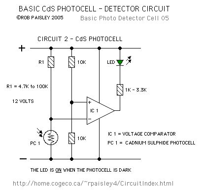
In this circuit, when the light falling on the photocell (PC 1) is blocked, its resistance will increase and the voltage across PC 1 will rise. When the voltage rises above 1/2 of the supply voltage the output of the comparator will turn ON and the LED will be lit.
Due to wide variations in CdS photocells it is usually best to install the cell and then measure its resistance under normal lighting conditions. A resistor with a value that is approximately 3 to 5 times the measured resistance of the cell is then selected for R1. For example; If the cell resistance is measured at 400 ohms then a 1200 to 2200 ohms resistor would be used.
Increasing the value of R1 will cause the sensitivity of the sensor to decrease. This may be necessary when the light falling on the cell is not very strong or shadows can affect the photocell.
This circuit can be adapted for use in dark areas by placing a small light above the photocell. (View)
View full Circuit Diagram | Comments | Reading(1196)
Visible Light Photo-Detector Circuits
Published:2013/6/6 20:30:00 Author:muriel | Keyword: Visible Light, Photo-Detector Circuits

View full Circuit Diagram | Comments | Reading(892)
Stepper motors
Published:2013/6/6 20:27:00 Author:muriel | Keyword: Stepper motors

View full Circuit Diagram | Comments | Reading(764)
Low Voltage Motors
Published:2013/6/6 20:27:00 Author:muriel | Keyword: Low Voltage Motors

View full Circuit Diagram | Comments | Reading(516)
Fast External Clock
Published:2013/6/6 20:26:00 Author:muriel | Keyword: Fast External Clock
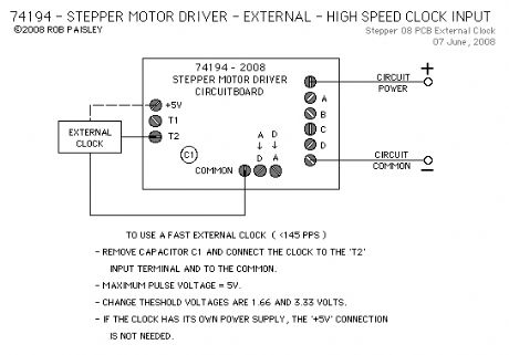
View full Circuit Diagram | Comments | Reading(909)
Slower Step Rates
Published:2013/6/6 20:25:00 Author:muriel | Keyword: Slower Step Rates
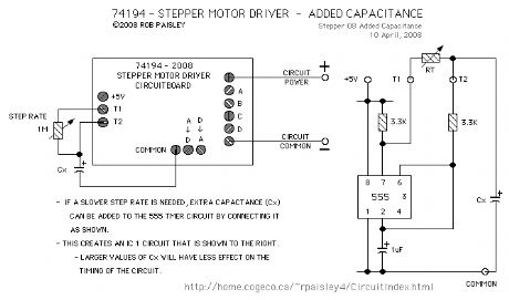
View full Circuit Diagram | Comments | Reading(500)
| Pages:100/2234 At 2081828384858687888990919293949596979899100Under 20 |
Circuit Categories
power supply circuit
Amplifier Circuit
Basic Circuit
LED and Light Circuit
Sensor Circuit
Signal Processing
Electrical Equipment Circuit
Control Circuit
Remote Control Circuit
A/D-D/A Converter Circuit
Audio Circuit
Measuring and Test Circuit
Communication Circuit
Computer-Related Circuit
555 Circuit
Automotive Circuit
Repairing Circuit