
Circuit Diagram
Index 98
Potentiometer Controlled Silicon Controlled Rectifier Throttle
Published:2013/6/7 21:34:00 Author:muriel | Keyword: Potentiometer Controlled, Silicon Controlled, Rectifier Throttle

View full Circuit Diagram | Comments | Reading(904)
Silicon Controlled Rectifier Model Railroad Throttles
Published:2013/6/7 21:33:00 Author:muriel | Keyword: Silicon Controlled, Rectifier Model, Railroad Throttles

The following is a schematic drawing of a Silicon Controlled Rectifier type throttle for use on larger scale model railroads. Three versions of this throttle are shown on this page. They are not sophisticated designs but work well and are tough and reliable.
It was designed for use on a The London Model Railroad Group's large O scale layout located at London, Ontario, Canada. The prime requirements for the club throttles were that they be rugged, reliable and produce as little heat as possible. Throttles of this type have been in service at the club since 1987 with excellent results. The throttle will deliver 5 amps continuously and up to 18 volts DC. See Notes.
The Programmable Unijunction Transistor used to trigger the SCR is the key to this design as it ensures that the SCR fires on every cycle of the fullwave DC. This gives a very efficient operation with low voltage loss and very little heat generated. Please refer to your electronics books if you need more information on how the SCR and PUJT in the circuit function.
The SCR throttle has momentum effect built in due to the memory provided by the 50uF capacitor at the PLUS input of the OPAMP. There is no decay but this can be added by placing a 1 to 2 Megohm resistor in parallel with the 50uF capacitor. Increasing the value of the memory capacitor will slow the action of the throttle controls.
Due to its unregulated voltage output, the SCR throttle will have a prototypical feel as trains will slow when climbing grades and speed up when going down grades. The operator must work the throttle to keep their train from speeding or slowing too much in hilly terrain.
SCR Throttle Setup Instructions
The 50K Trimmer is adjusted so that maximum output voltage can be obtained but keep the SCR triggering on each cycle. To do this perform the following steps.
1. With no load connected to the throttle output and the AC input turned on.
2. Connect an analog voltmeter to the output of the throttle (0-30V).
3. Set the trimmer to its maximum resistance.
4. Press and hold the ACCELERATE push button until the output voltage stops increasing.
5. DECREASE the resistance of the trimmer until the output voltage peaks and then begins to fall again. When the voltmeter needle starts to bounce slightly the SCR is at its maximum trigger angle. STOP.
6. INCREASE the resistance of the trimmer slightly until the meter needle stops bouncing. At this setting the throttle will be able to deliver its maximum voltage. If the trimmer resistance is set too low the SCR will not trigger on every cycle of the full wave DC at full output voltage and could be damaged by high current spikes.
Notes
* NOTE 1 At full throttle and with no load this circuit will deliver more than 25 volts. Therefore care must be taken with auxiliary equipment and train lighting that may be connected to the track.
(Remember that most voltmeters only indicate average or RMS voltage and not the peak voltage which can be 1.4 times greater that the average.)
* NOTE 2 If your trains will run as fast as you need at lower track voltages than 18 volts then lower the input to 12 or 14 volts AC. The under load DC output voltage of this type of throttle is roughly equal to the RMS AC input voltage.
* NOTE 3 Add your own reversing switches to the output and a suitable circuit breaker for added protection if desired.
* NOTE 4 The use of good quality push buttons is a must as these are the most likely components of the throttle to fail due to the heavy thumbs of some people.
Please feel free to use this design if you wish. It worked for our club it might be useful to you. (View)
View full Circuit Diagram | Comments | Reading(1656)
A Three Terminal Regulator Type Throttle
Published:2013/6/7 21:32:00 Author:muriel | Keyword: Three Terminal, Regulator Type , Throttle

The schematic above is of a Three Terminal Regulator (TTR) design based on the LM350K adjustable voltage regulator which has a 3 Amp current rating as opposed to the LM317K with a 1.5 Amp rating. The LM 350 is internally protected from current and thermal overload and can be thought of as a high current version of the LM 317.
With the component values shown the circuit is designed to have and output voltage range of approximately 1.25 to 13.5 Volts when measured at the output of the regulator. The calculation on the drawing is used to determine the output voltage for given values of R1 and R2.
Because these regulators have a minimum output voltage of 1.25 Volts diodes D3 and D4 will provide a voltage drop of approximately 1.4 Volts so that zero output to the track can be obtained. These diodes need to have at least a 3 amp rating
The diodes D1 and D2 added to the circuit will prevent damage to the regulator during certain adverse conditions such as the output voltage being higher than the input voltage to the regulator. This can happen if this type of circuit is used as a variable power supply for an electronics test bench and without the added protection of D3 and D4.
A substantial heat sink will be needed for the TTR as quite a bit of heat will be generated when drawing high current with low output voltages. For this reason this circuit is not recommended for use in hand held throttles.
If the less expensive LM 317 regulator is used this circuit makes an excellent test bench power supply just leave out D3 and 4 and add a voltmeter. (View)
View full Circuit Diagram | Comments | Reading(1195)
DC Throttle Circuits With Injected Pulses
Published:2013/6/7 21:31:00 Author:muriel | Keyword: DC Throttle Circuits, Injected Pulses


The following circuit is a straight DC version of the fullwave circuits above.
A varialable level, 60Hz pulse injection scheme is also included, this could be used to boost the output voltage in difficult areas of track, used to make the locomotive creep or perhaps as a kicker when shunting.
The same basic throttle as above but with push button controls. (View)
View full Circuit Diagram | Comments | Reading(1309)
basic throttle
Published:2013/6/7 21:30:00 Author:muriel | Keyword: basic throttle

View full Circuit Diagram | Comments | Reading(704)
Fullwave DC Throttle Circuits
Published:2013/6/7 21:30:00 Author:muriel | Keyword: Fullwave DC Throttle Circuits

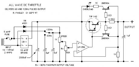
The following circuits are variations of a full wave DC throttles. The output voltage is clipped at a voltage level determined the 1K potentiometer so that the waveform is flat for most of the cycle. These throttles have good slow speed operation for typical DC motors.
A varialable level, 60Hz pulse injection scheme is also included, this could be used to boost the output voltage in difficult areas of track, used to make the locomotive creep or perhaps as a kicker when shunting. (View)
View full Circuit Diagram | Comments | Reading(785)
Full Featured Toy Throttle (Mk II)
Published:2013/6/7 21:29:00 Author:muriel | Keyword: Full Featured Toy Throttle (Mk II)

The next schematic shows a full featured Toy Throttle Upgrade. This version has Zero Indication, and Momentum.
The transformer and bridge rectifier have been omitted to make the drawing smaller.
All of the features in this circuit can be found in conventional throttle designs. The only difference here is the PLUS or MINUS output voltage capability. (View)
View full Circuit Diagram | Comments | Reading(738)
Toy Throttle with Zero Indication
Published:2013/6/7 21:29:00 Author:muriel | Keyword: Toy Throttle , Zero Indication


With this type of throttle would be difficult to know when the output is at ZERO . To help with this a ZERO indicator has been added to the next drawing. The indicator can also show the trains direction.
The above schematic shows the addition of a Zero Indicating circuit to the throttle. When the output voltage is between +0.7 and -0.7 Volts both of the LED's, D3/4 will be OFF. As the output voltage increases, either PLUS or MINUS, one of the LED's will turn ON.
This will allow the operator to know when the throttle's output voltage is near ZERO and the train is safely stopped.
As there are two LED's, they can also show the direction of travel based on the polarity of the output voltage.
A two colour LED could be used for D3/4. This will give a GREEN indication for one direction and a RED indication for the other.
The next schematic shows an optional ZERO indication method. In this case the LED will be ON when the throttles output is near ZERO.
(View)
View full Circuit Diagram | Comments | Reading(507)
Basic Toy Throttle - Push Button Control
Published:2013/6/7 21:28:00 Author:muriel | Keyword: Basic Toy Throttle , Push Button Control
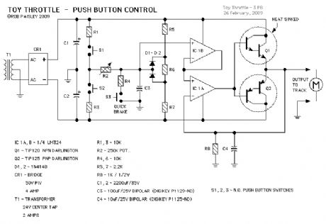
This next circuit is a variation on the Basic Toy throttle. In this version three push buttons are used to control the output.
Button S1 causes the train to move in one direction while S2 moves it in the other. Button S3 is the Quick or emergency brake that will stop the train very quickly.
An interesting feature of this system is that the train could be brought to a stop and then move off in the opposite direction by pressing only one button. Useful for shunting perhaps.
Resistors R5, R6, R7 and diodes D1, D2 form a voltage limiter that reduces the maximum output voltage swing as mentioned in the potentiometer controlled circuit description. (View)
View full Circuit Diagram | Comments | Reading(1101)
Basic Toy Throttle
Published:2013/6/7 21:27:00 Author:muriel | Keyword: Basic Toy Throttle

The above schematic shows the basic Toy Throttle. It is powered by a 24 Volts AC, Center Tapped transformer to provide PLUS and MINUS voltages.
The throttle uses a Push-Pull amplifier that eliminates the need for a reversing relay or switch.
When resistor R2 is in the CENTER position the throttles output voltage would be ZERO . Adjusting R2 up or down would produce positive or negative voltage to the track thereby controlling the trains direction.
Resistors R1 and R3 limit the maximum output voltage to between PLUS or MINUS 10 Volts. (View)
View full Circuit Diagram | Comments | Reading(689)
A Regulated Current Pulse Throttle
Published:2013/6/7 21:27:00 Author:muriel | Keyword: A Regulated Current Pulse Throttle

The next throttle is more than a little different, it's very different but in its own unique way it works just fine. It is however posted here for interest sake only and should not be viewed as a major discovery or some sort of magic trick.
The design uses the variable pulse width oscillator that is the at the heart of the Variable Pulse Type Throttle as shown above. The oscillator in this circuit however switches a current regulator constructed from an LM317 voltage regulator.
Rather than regulating the output voltage this throttle instead produces variable width pulses of a fixed current value, for example 200 or 400mA. The voltage can rise to a level that is determined largely by the B+ input voltage and the drop across the LM317 but the motor can only receive the maximum current that the LM317 will pass. This current value is determined by the value of R1. (View)
View full Circuit Diagram | Comments | Reading(665)
A Variable Width Pulse Type Throttle
Published:2013/6/7 21:26:00 Author:muriel | Keyword: Variable Width Pulse Type Throttle
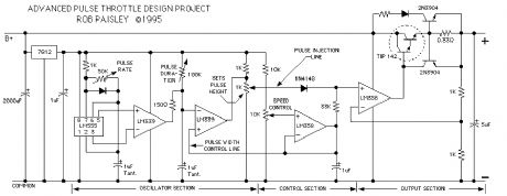
The next schematic is for an advanced type of pulse throttle. Simply put, as the output voltage is increased by the 10K pot, a pulse is injected onto the the control voltage at the PLUS input terminal of the second LM358 OpAmp. As the control voltage increases the width of the pulse is also increased. (View)
View full Circuit Diagram | Comments | Reading(760)
All-wave DC Throttle Schematic
Published:2013/6/7 21:24:00 Author:muriel | Keyword: All-wave DC Throttle Schematic
View full Circuit Diagram | Comments | Reading(983)
Unplugable Walk Around Control and Delayed Reversing Schematic
Published:2013/6/7 21:24:00 Author:muriel | Keyword: Unplugable Walk Around Control , Delayed Reversing Schematic

next up is the basic transistor throttle with unplugable walk around control added. The direction memory uses an LM339 quad comparator and has a delayed action so that the direction can not change if the throttle output is above a predetermined voltage.
The delayed reverse section, comparator section D, of the circuit grounds the bases of the transistors whenever the voltage at its PLUS input is higher than the reference voltage at the MINUS input. The PLUS input is connected to the throttle control voltage line.
When the transistor bases are grounded they cannot conduct and any changes at their emitters will have no effect until the control voltage again falls below the preset level.
Comparator sections B and C function as a voltage window detector. That is to say the outputs of both section Band C are high as long as the direction signal voltage is between 4 and 8 volts. If the signal goes below 4 volts or above 8 volts the appropriate output will go low and the direction will change accordingly.
If the controller is unplugged the direction signal will go to 6 volts and the train will maintain its last direction.
Please refer to the voltage comparator information page on this web site for help on how comparators work. (View)
View full Circuit Diagram | Comments | Reading(989)
Auxiliary Output Schematic
Published:2013/6/7 21:23:00 Author:muriel | Keyword: Auxiliary Output Schematic
View full Circuit Diagram | Comments | Reading(751)
Auxiliary Throttle Controls
Published:2013/6/7 21:23:00 Author:muriel | Keyword: Auxiliary Throttle Controls

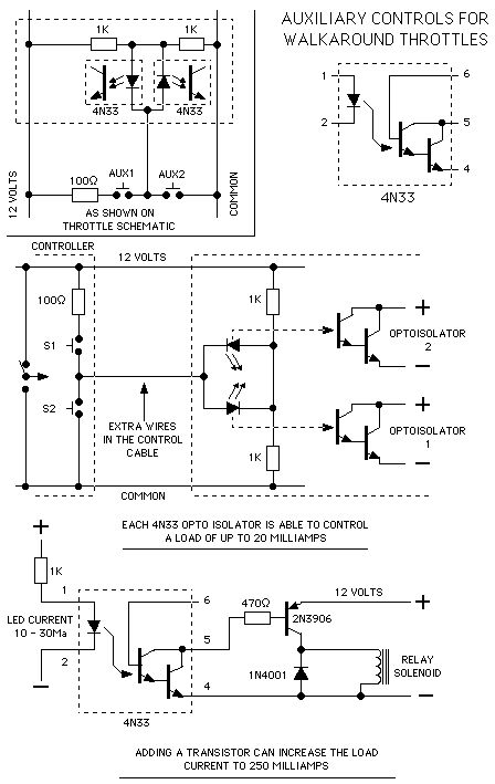
A variation on the walkaround throttle is in the next circuit. If extra wires are added to the control cable they can be put to use for operating accessories on the layout.
For every extra wire 2 such loads can be controlled. Electromagnetic uncoupling ramps could be turned on and off, train whistles could be blown or a reverse loop switch can be thrown after the train has passed.
(View)
View full Circuit Diagram | Comments | Reading(1078)
Walkaround Control for The Basic Throttle
Published:2013/6/7 21:23:00 Author:muriel | Keyword: Walkaround Control , Basic Throttle

In the next circuit walk around control is added to the throttle. A 4 conductor, 22 Gauge stranded cable will allow the operator to move around with the 'Hand Held Controller' while the power section of the throttle remains at a fixed location.
A DPDT 24 Volt DC relay and a toggle switch has been added for direction control. The direction switch, speed control potentiometer and a 10K ohm resistor are mounted in the Hand Held Controller. (View)
View full Circuit Diagram | Comments | Reading(817)
The Basic Throttle
Published:2013/6/7 21:22:00 Author:muriel | Keyword: The Basic Throttle
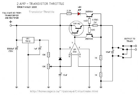
The first circuit is a 2 Amp, 0-12 Volt, voltage regulator type circuit. It uses a 10K ohm potentiometer to control the output voltage and has a light emitting diode that will indicate an overload condition. A DPDT toggle switch controls the train direction. The TIP142 output transistor will need a heat sink to keep it cool and the 0.33 ohm resistor should have a 5 Watt power rating. The OPAMP is one half of an LM 358. One quarter of a LM 324 could also be used.
(View)
View full Circuit Diagram | Comments | Reading(754)
Fixed Voltage Regulators 5 Or 12 Volt Supply
Published:2013/6/7 21:21:00 Author:muriel | Keyword: Fixed Voltage Regulators, 5 Or 12 Volt Supply
View full Circuit Diagram | Comments | Reading(1071)
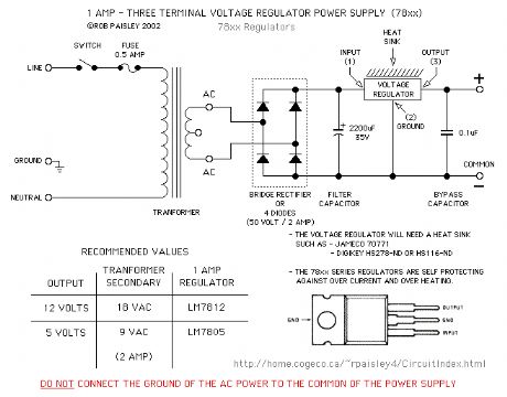
Throttle Power Supply
Published:2013/6/7 21:20:00 Author:muriel | Keyword: Throttle Power Supply

The first schematic is of the Direct Current power supply for the throttles. Shown is the primary and secondary circuits and the components needed to power the throttles. As this section of the throttles uses 120 volt AC power great caution should be taken in this area. All transformers should be mounted in a fully enclosed metal cabinet and properly grounded. Transformers for multiple units could be centrally located and the low voltage AC then routed to each throttle.
(View)
View full Circuit Diagram | Comments | Reading(915)
| Pages:98/2234 At 2081828384858687888990919293949596979899100Under 20 |
Circuit Categories
power supply circuit
Amplifier Circuit
Basic Circuit
LED and Light Circuit
Sensor Circuit
Signal Processing
Electrical Equipment Circuit
Control Circuit
Remote Control Circuit
A/D-D/A Converter Circuit
Audio Circuit
Measuring and Test Circuit
Communication Circuit
Computer-Related Circuit
555 Circuit
Automotive Circuit
Repairing Circuit