Basic Circuit
The Basic Throttle
Published:2013/6/7 21:22:00 Author:muriel | Keyword: The Basic Throttle | From:SeekIC

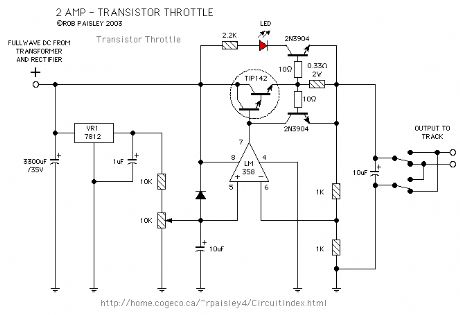
The first circuit is a 2 Amp, 0-12 Volt, voltage regulator type circuit. It uses a 10K ohm potentiometer to control the output voltage and has a light emitting diode that will indicate an overload condition. A DPDT toggle switch controls the train direction. The TIP142 output transistor will need a heat sink to keep it cool and the 0.33 ohm resistor should have a 5 Watt power rating. The OPAMP is one half of an LM 358. One quarter of a LM 324 could also be used.
Reprinted Url Of This Article:
http://www.seekic.com/circuit_diagram/Basic_Circuit/The_Basic_Throttle.html
Print this Page | Comments | Reading(3)

Article Categories
power supply circuit
Amplifier Circuit
Basic Circuit
LED and Light Circuit
Sensor Circuit
Signal Processing
Electrical Equipment Circuit
Control Circuit
Remote Control Circuit
A/D-D/A Converter Circuit
Audio Circuit
Measuring and Test Circuit
Communication Circuit
Computer-Related Circuit
555 Circuit
Automotive Circuit
Repairing Circuit
Code: