
Circuit Diagram
Index 82
LED5S12V Modified for use with a PLC
Published:2013/7/5 1:38:00 Author:muriel | Keyword: LED5S12V, Modified, PLC

The schematic is for the Pull Down variant.
This version of the basic LED5 can be used as a sensor input to a PLC, Programmable Logic Controller. The output is an Open Collector NPN transistor and assumes the PLC has the associated Pull Up resistors.
The actual voltage range is from 4V to 28V. (I can make higher voltage variants also.)
I can also make 24V LED5 trackers with totem pole outputs which have both pullup and pulldown transistors. Essentially the same as the standard trackers but with limited drive capabilities.
This circuit does not have a parking function. Parking and Reverse Inhibit functions are best performed in the software of the PLC using timing functions.
Note! If you don't want the 4.7KΩ or 5.1KΩ 1/6thW passive load resisters they can be removed by clipping one of the resister leads. (View)
View full Circuit Diagram | Comments | Reading(780)
LED5 Connections
Published:2013/7/5 1:38:00 Author:muriel | Keyword: LED5 Connections
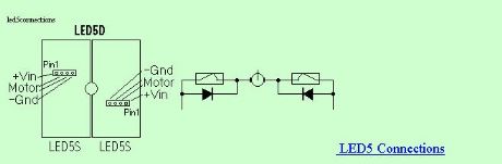
View full Circuit Diagram | Comments | Reading(668)
LED5S12V Simplified LED low power tracker
Published:2013/7/5 1:37:00 Author:muriel | Keyword: LED5S12V , Simplified , LED , low power , tracker

This circuit uses small switching transistors. The maximum motor drive current is limited to about 100mA maximum at 12V. (View)
View full Circuit Diagram | Comments | Reading(880)
LED5S5V Simplified LED low power tracker
Published:2013/7/5 1:36:00 Author:muriel | Keyword: LED5S5V, Simplified, LED , low power tracker
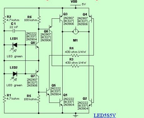
I was looking for a much lower cost tracker for low power applications. One of these applications is a small lighting heliostat. This circuit uses small switching transistors. The maximum motor drive current is limited to about 250mA maximum at 5V.
I've tested the circuit on voltages from 3V to 21V. With some component changes it should be useful to 63V in a 36V PV panel system although I haven't tried this yet. With higher voltage and the use of heat sinks on the bridge transistors much higher currents should be possible. (View)
View full Circuit Diagram | Comments | Reading(1244)
LED2 LED Sensor Relay Tracker Schematic
Published:2013/7/5 1:35:00 Author:muriel | Keyword: LED2 , LED, Sensor , Relay, Tracker Schematic
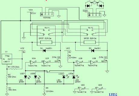
Circuit 1 tends to chatter the relays under certain lighting conditions as there is no built in hysteresis. This version uses a Schmitt trigger hex inverter circuit to eliminate the chatter. It works better but is more complex.
Note! R4 and R5 are used to force parking when it gets dark. If parking is not desired don't use R4 and R5. Parking may not be desired in low power consumption applications.Also, the parking resistors, R4 and R5, reduce sensitivity a bit. (View)
View full Circuit Diagram | Comments | Reading(981)
LED1 LED Sensor Relay Tracker Schematic
Published:2013/7/5 1:35:00 Author:muriel | Keyword: LED1 , LED , Sensor, Relay , Tracker Schematic
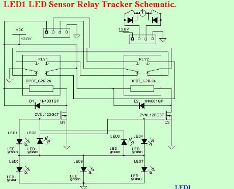
I have been looking for truly low cost and yet accurate conventional solar trackers. The CdS tracker is pretty good but lacks accuracy and sensitivity. I was thinking about using PV cells as the sensor. I was experimenting with LEDs and noticed they generate voltage in sunlight.
Bingo! This got me to thinking.
They generate quite a bit of voltage. The green ones generate about 1.65V, some as much a 1.74V. Not the piddley .55 volts of a silicon PV cell. How is this so? Well, it turns out green LEDs are made from Gallium Phosphide, a semiconductor with a much higher bandgap voltage.
I thought I had invented the use of LEDs as PV cells as I had never heard of this effect before. Well, after some investigating I found a number of references to this. The guys that had done the most work in this area were the people form the BEAM project. They make tiny solar powered robots and some used LED photo sensors.
I had been using a very low threshold MOSFET in a TO-92 package, BS107PT. The threshold is about 1.5V. If I put two LEDs back to back, one fighting the other, the one with more light intensity wins. I thought I could use this to switch the MOSFET. And it worked.
By using one LED as a sort of power supply and the back to back pair connected from it to the MOSFET gate the circuit is complete. (This I have not seen elsewhere.) My implementation uses three power supply LEDs, aimed East, Up, and West. The sensor LEDs are aimed about 90°s from each other and at about 45°s either side of up. Of course the easterly pair will be a little to the East and the westerly pair a little to the West. This makes the center have a dead zone where tracking stops.
The circuit is quite sensitive. It brings the panel back to the East just after sun rise. The accuracy is quite good. You can calibrate the sensor by bending or aiming the LEDs a bit.
While the proof of concept is good it will burn the relay contacts, similar to that on the Cadmium Sulfide tracker. This is caused by the relays being turned on or off slowly. It melted the plastic case on the relays. (View)
View full Circuit Diagram | Comments | Reading(1098)
How Limit Switches Operate
Published:2013/7/5 1:34:00 Author:muriel | Keyword: Limit Switches
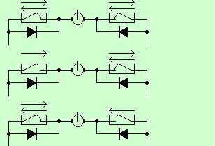
Limit switches are essential for servo motor operation with solar trackers. I made this diagram to help explain how they work.
Top. Normal operation between limit switches.Middle. The left limit switch has opened to stop movement to the left. To move to the right again the diode conducts current that allows movement to the right.Bottom. The right limit switch has opened to stop movement to the right. To move to the left again the diode conducts current that allows movement to the left.
Sellect a diode or rectifier rated at the maximum motor current plus some margine. Also the voltage should be at leat 100V and preferably 200V.
Needles to say, the limit switch must operate before the mechanical limits are reached. If the mechanical stop is reached before the switch the motor can draw quite high currents and can destroy the solar tracker. (View)
View full Circuit Diagram | Comments | Reading(1088)
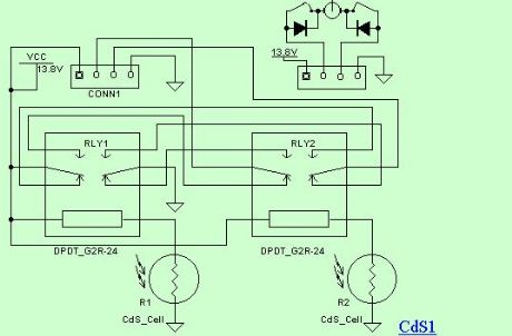
Cadmium Sulfide Relay Tracker Schematic
Published:2013/7/5 1:33:00 Author:muriel | Keyword: Cadmium Sulfide, Relay , Tracker Schematic
View full Circuit Diagram | Comments | Reading(823)
Light sensors
Published:2013/7/5 1:33:00 Author:muriel | Keyword: Light sensors

View full Circuit Diagram | Comments | Reading(1179)
IO Bit Serial Interface Schematic
Published:2013/7/5 1:32:00 Author:muriel | Keyword: IO Bit , Serial , Interface Schematic

View full Circuit Diagram | Comments | Reading(669)
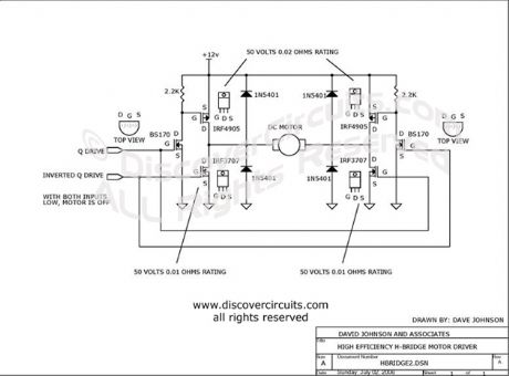
Low Voltage H-bridge circuits
Published:2013/7/5 1:30:00 Author:muriel | Keyword: Low Voltage, H-bridge circuits
View full Circuit Diagram | Comments | Reading(698)
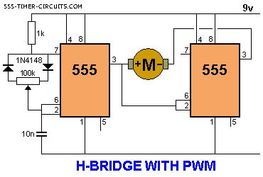
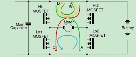
H-BRIDGE WITH PWM Circuit
Published:2013/7/3 3:04:00 Author:muriel | Keyword: H-BRIDGE, PWM Circuit
View full Circuit Diagram | Comments | Reading(769)
H-Bridges: Theory and Practice
Published:2013/7/3 3:03:00 Author:muriel | Keyword: H-Bridges
View full Circuit Diagram | Comments | Reading(697)
H bridge switch
Published:2013/7/3 3:03:00 Author:muriel | Keyword: H bridge switch
View full Circuit Diagram | Comments | Reading(1011)
H-Bridge Power Amp
Published:2013/7/3 3:02:00 Author:muriel | Keyword: H-Bridge Power Amp

View full Circuit Diagram | Comments | Reading(997)
H Bridge Motor control
Published:2013/7/3 3:01:00 Author:muriel | Keyword: H Bridge Motor control
View full Circuit Diagram | Comments | Reading(973)
Darlington power transistors
Published:2013/7/3 3:00:00 Author:muriel | Keyword: Darlington power transistors
View full Circuit Diagram | Comments | Reading(673)
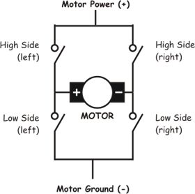
H-Bridge
Published:2013/7/3 3:00:00 Author:muriel | Keyword: H-Bridge
View full Circuit Diagram | Comments | Reading(685)
H-BRIDGE Circuits
Published:2013/7/3 2:59:00 Author:muriel | Keyword: H-BRIDGE Circuit
View full Circuit Diagram | Comments | Reading(623)
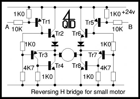
Bruce Robinson's "Full-featured" Dual H-bridge
Published:2013/7/3 2:58:00 Author:muriel | Keyword: "Full-featured" Dual H-bridge
View full Circuit Diagram | Comments | Reading(0)
| Pages:82/2234 At 2081828384858687888990919293949596979899100Under 20 |
Circuit Categories
power supply circuit
Amplifier Circuit
Basic Circuit
LED and Light Circuit
Sensor Circuit
Signal Processing
Electrical Equipment Circuit
Control Circuit
Remote Control Circuit
A/D-D/A Converter Circuit
Audio Circuit
Measuring and Test Circuit
Communication Circuit
Computer-Related Circuit
555 Circuit
Automotive Circuit
Repairing Circuit