Control Circuit
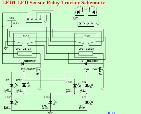
LED1 LED Sensor Relay Tracker Schematic
Published:2013/7/5 1:35:00 Author:muriel | Keyword: LED1 , LED , Sensor, Relay , Tracker Schematic | From:SeekIC

I have been looking for truly low cost and yet accurate conventional solar trackers. The CdS tracker is pretty good but lacks accuracy and sensitivity. I was thinking about using PV cells as the sensor. I was experimenting with LEDs and noticed they generate voltage in sunlight.
Bingo! This got me to thinking.
They generate quite a bit of voltage. The green ones generate about 1.65V, some as much a 1.74V. Not the piddley .55 volts of a silicon PV cell. How is this so? Well, it turns out green LEDs are made from Gallium Phosphide, a semiconductor with a much higher bandgap voltage.
I thought I had invented the use of LEDs as PV cells as I had never heard of this effect before. Well, after some investigating I found a number of references to this. The guys that had done the most work in this area were the people form the BEAM project. They make tiny solar powered robots and some used LED photo sensors.
I had been using a very low threshold MOSFET in a TO-92 package, BS107PT. The threshold is about 1.5V. If I put two LEDs back to back, one fighting the other, the one with more light intensity wins. I thought I could use this to switch the MOSFET. And it worked.
By using one LED as a sort of power supply and the back to back pair connected from it to the MOSFET gate the circuit is complete. (This I have not seen elsewhere.) My implementation uses three power supply LEDs, aimed East, Up, and West. The sensor LEDs are aimed about 90°s from each other and at about 45°s either side of up. Of course the easterly pair will be a little to the East and the westerly pair a little to the West. This makes the center have a dead zone where tracking stops.
The circuit is quite sensitive. It brings the panel back to the East just after sun rise. The accuracy is quite good. You can calibrate the sensor by bending or aiming the LEDs a bit.
While the proof of concept is good it will burn the relay contacts, similar to that on the Cadmium Sulfide tracker. This is caused by the relays being turned on or off slowly. It melted the plastic case on the relays.
Reprinted Url Of This Article:
http://www.seekic.com/circuit_diagram/Control_Circuit/LED1_LED_Sensor_Relay_Tracker_Schematic.html
Print this Page | Comments | Reading(3)

Article Categories
power supply circuit
Amplifier Circuit
Basic Circuit
LED and Light Circuit
Sensor Circuit
Signal Processing
Electrical Equipment Circuit
Control Circuit
Remote Control Circuit
A/D-D/A Converter Circuit
Audio Circuit
Measuring and Test Circuit
Communication Circuit
Computer-Related Circuit
555 Circuit
Automotive Circuit
Repairing Circuit
Code: