
Circuit Diagram
Index 83
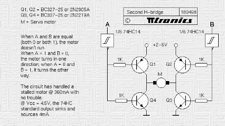
Steve Bolt's 4-transistor H-bridge
Published:2013/7/3 2:58:00 Author:muriel | Keyword: 4-transistor H-bridge
View full Circuit Diagram | Comments | Reading(0)
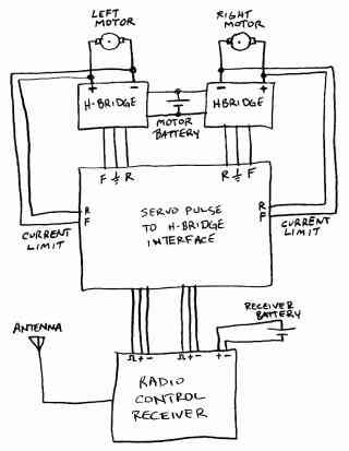
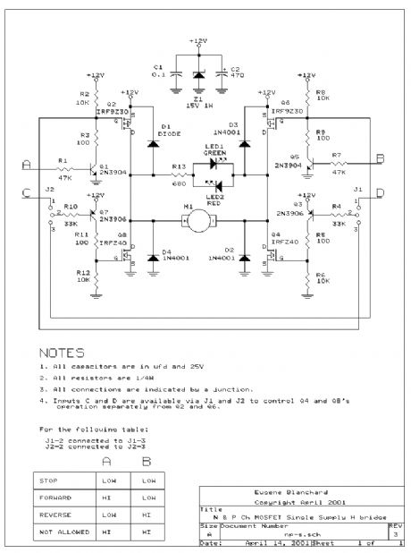
Dual Channel Servo Pulse to H-Bridge Interface
Published:2013/7/3 2:57:00 Author:muriel | Keyword: Dual Channel, Servo Pulse , H-Bridge Interface
View full Circuit Diagram | Comments | Reading(579)
Low Voltage H-bridge circuit
Published:2013/7/3 2:56:00 Author:muriel | Keyword: Low Voltage , H-bridge
View full Circuit Diagram | Comments | Reading(790)
Transistor Control
Published:2013/7/3 2:54:00 Author:muriel | Keyword: Transistor Control

View full Circuit Diagram | Comments | Reading(949)
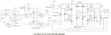
Alternating CW & CCW Motor Driver
Published:2013/7/3 2:53:00 Author:muriel | Keyword: Alternating, CW & CCW , Motor , Driver
View full Circuit Diagram | Comments | Reading(1483)
H-Bridge Circuit
Published:2013/7/3 2:51:00 Author:muriel | Keyword: H-Bridge Circuit
View full Circuit Diagram | Comments | Reading(2110)
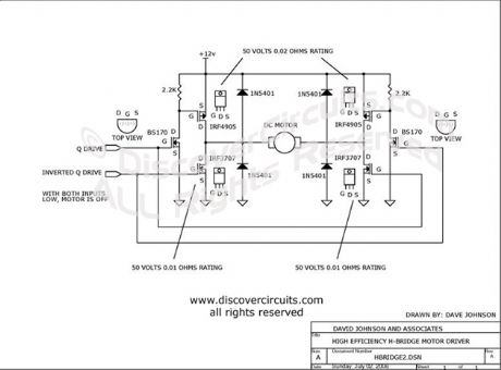
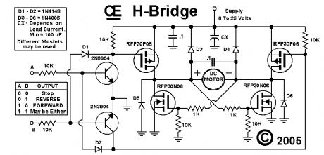
better MOSFET H Bridge Schematic
Published:2013/7/3 2:50:00 Author:muriel | Keyword: better MOSFET , H Bridge Schematic
View full Circuit Diagram | Comments | Reading(702)
Power switching circuits
Published:2013/7/3 2:48:00 Author:muriel | Keyword: Power switching circuits
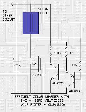
The Zero Volt Diode -- a synchronous rectifier circuit by Wilf Rigter:
The Zero Volt Diode (ZVD) is a circuit useful in a variety of applications including solar chargers of all types. It is a novel circuit in which a power MOSFET acts like a very low voltage drop diode that switches state at 0V and which is used to conduct negative current from drain to source.
In D1 type solar engines, a low loss diode can be used to charge a cap to the open circuit voltage of the solar cell and used in solar battery chargers, the battery is charged at the maximum rate when the source voltage is highest. The diode must be used in series with the solar panel or else the cap or battery would discharge through the solar panel when the panel voltage drops below the stored voltage. The diode or equivalent polarity sensitive switch is therefore essential to solar chargers.
Most diodes used in BEAM SEs and solar chargers are Silicon diodes like the 1N4001 which have a voltage drop of 0.6V to 1V at currents up to 1A. More efficient diodes for currents form >100mA to tens of amps applications are the Schottky type rectifiers with a voltage drop of from 200mV to 1000mV depending on the current level. For <100mA applications a Germanium diode can used with 200mV or less drop.
This voltage drop issue is important in competition solar engines since you would like to have the maximum voltage to charge the cap and supply the load (low diode drop) and keep the charge stored on the cap when the lightlevel drops (leakage current cut off) and the SE triggers. Moreover, since the energy in the cap is proportional to the square of the voltage even the small voltage drop of a diode reduces available energy. One obvious simple improvement over the original D1 design is to substitute a Ge 1N34A diode (Radio Shack) instead of the Si 1N4001 diode.
An ideal diode would have zero voltage drop. While a straight hookup of the solar cell has minimum voltage drop it leaks if the light drops and any real diode has a forward voltage drop. What to do?
The solution is to use a MOSFET as a rectifier just like the synchronous rectifier applications in voltage converters. The MOSFET should be switched ON when the solar voltage is larger than the capacitor or battery voltage and switch OFF when the solar voltage is lower than the stored voltage.
Here is a little design for charging capacitors from solar cells with zero voltage drop at the end of the charge cycle. It can be easily scaled to higher currents by changing the 2N7000 for a larger MOSFET. If a parallel load is present, the circuit also delivers maximum voltage with minimum insertion loss from the solar cell. The MOSFET turns on when the voltage difference is zero and turns off when the solar voltage drops less than 100mV below the cap or battery.
The NPN transistor is normally ON when the cap voltage is more than .6V and this clamps the gate of the 2N7000 which is turned OFF. The PNP transistor is connected to the negative terminal of the solar panel and when the voltage on that terminal drops below 0V the PNP turns ON. This in turn turns the NPN OFF and the 2N7000 turns ON. MOSFETs have an interesting characteristic in that they act like bi-directional switches, so the 2N7000 is perfectly happy to have it's drain conduct a negative current to the 0V line. When the voltage on the negative terminal of the solar panel is more positive than 0V the PNP turns OFF and the NPN ON and the 2N7000 turns off with the drain voltage positive with respect to the source voltage and 0V line. Since the 2N7000 does not turn on until the gate voltage is more than 2V (in practice: higher according to the data book) a logic FET with a lower gate turn on voltage would be preferred. In any case the MOSFET has a integral reverse diode from drain to source which will carry the current until the voltage on the cap reaches 2V at which point the MOSFET turns on and the forward voltage drops to a few 10s of mV. (View)
View full Circuit Diagram | Comments | Reading(1284)
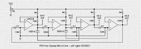
Opamp microcore circuit
Published:2013/7/3 2:46:00 Author:muriel | Keyword: Opamp microcore circuit
View full Circuit Diagram | Comments | Reading(997)
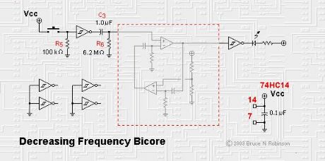
Decreasing Frequency Bicore
Published:2013/7/3 2:46:00 Author:muriel | Keyword: Decreasing Frequency Bicore
View full Circuit Diagram | Comments | Reading(592)
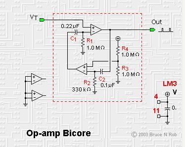
Op-amp Bicore
Published:2013/7/3 2:45:00 Author:muriel | Keyword: Op-amp Bicore
View full Circuit Diagram | Comments | Reading(894)
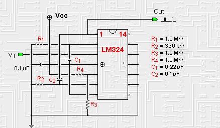
Op-amp based Nv nets
Published:2013/7/3 2:44:00 Author:muriel | Keyword: Op-amp , Nv nets
View full Circuit Diagram | Comments | Reading(1137)
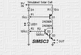
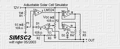
Solar cell simulators 3
Published:2013/7/3 2:44:00 Author:muriel | Keyword: Solar cell simulators
View full Circuit Diagram | Comments | Reading(1196)
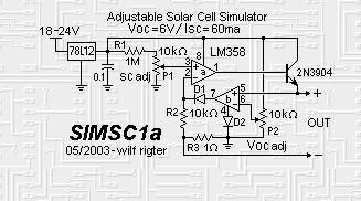
Solar cell simulators 2
Published:2013/7/3 2:43:00 Author:muriel | Keyword: Solar cell simulators
View full Circuit Diagram | Comments | Reading(518)
Solar cell simulators
Published:2013/7/3 2:43:00 Author:muriel | Keyword: Solar cell simulators
View full Circuit Diagram | Comments | Reading(533)
PC Board Layout and Parts Placement
Published:2013/7/3 2:42:00 Author:muriel | Keyword: PC Board Layout, Parts Placement
View full Circuit Diagram | Comments | Reading(585)
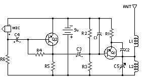
simple 1.5 Volt tracking transmitter.
Published:2013/7/3 2:42:00 Author:muriel | Keyword: 1.5 Volt, tracking transmitter.

View full Circuit Diagram | Comments | Reading(1162)
Schematic For Receiver 2
Published:2013/7/3 2:40:00 Author:muriel | Keyword: Receiver

View full Circuit Diagram | Comments | Reading(806)
Schematic For Receiver
Published:2013/7/3 2:40:00 Author:muriel | Keyword: Receiver
View full Circuit Diagram | Comments | Reading(764)
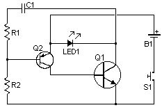
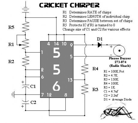
Backup circuit (chirper)
Published:2013/7/3 2:38:00 Author:muriel | Keyword: Backup circuit (chirper)
View full Circuit Diagram | Comments | Reading(752)
| Pages:83/2234 At 2081828384858687888990919293949596979899100Under 20 |
Circuit Categories
power supply circuit
Amplifier Circuit
Basic Circuit
LED and Light Circuit
Sensor Circuit
Signal Processing
Electrical Equipment Circuit
Control Circuit
Remote Control Circuit
A/D-D/A Converter Circuit
Audio Circuit
Measuring and Test Circuit
Communication Circuit
Computer-Related Circuit
555 Circuit
Automotive Circuit
Repairing Circuit