
Circuit Diagram
Index 97
3 Level Battery Voltage Alarm
Published:2013/6/13 1:35:00 Author:muriel | Keyword: 3 Level, Battery , Voltage Alarm

View full Circuit Diagram | Comments | Reading(880)
H-Bridge Made With A ULN2803 Peripheral Driver
Published:2013/6/13 1:31:00 Author:muriel | Keyword: H-Bridge, ULN2803 , Peripheral Driver
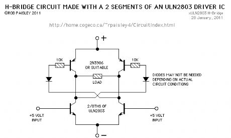
This is not a good design for an (or is it 'a') H-Bridge circuit but it's simple and will work well for low current loads.
The diodes in the base circuit of the PNP transistors might be needed to allow them to cut-off. The resistor in the base circuit depends on the gain of the transistors. A resistor from B+ to the top of the diodes may be needed as well.
The circuit as shown, was tested with a 10 volt supply driving a Tortoise® switch machine with series direction indictating LEDs. (View)
View full Circuit Diagram | Comments | Reading(1224)
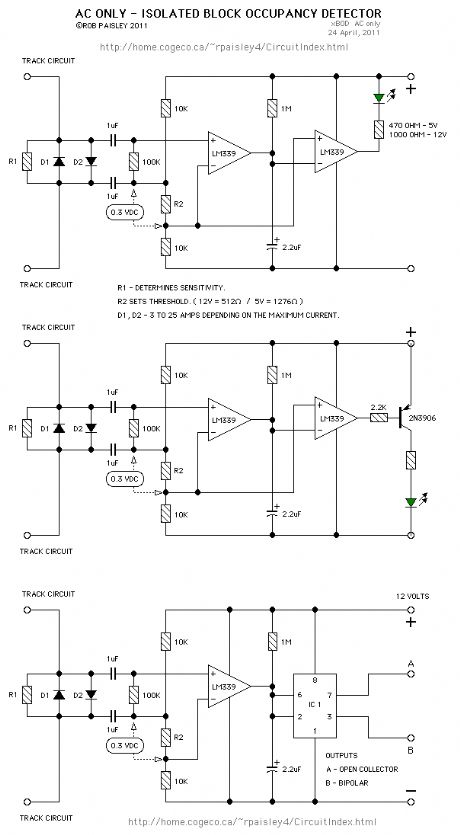
AC Only - Block Occupancy Detector
Published:2013/6/13 1:29:00 Author:muriel | Keyword: AC Only, Block Occupancy Detector
View full Circuit Diagram | Comments | Reading(1088)
DCC Inrush Current Limiter
Published:2013/6/13 1:29:00 Author:muriel | Keyword: DCC, Inrush Current Limiter
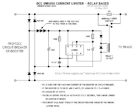
This circuit can be used with DCC boosters and circuit breakers to prevent them from tripping due to a sudden surge of current when power is applied to locomotives with sound cards that have large filter capacitors.
NOTE: This circuit has not been properly tested with sound decoders that have large filter capacitors but should work as intended.
NOTE: It may be possible to use a smaller value for R1.
(View)
View full Circuit Diagram | Comments | Reading(2374)
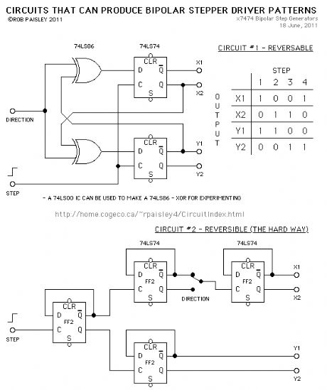
7474 Bipolar Stepper Driver Generators
Published:2013/6/13 1:27:00 Author:muriel | Keyword: 7474, Bipolar, Stepper Driver, Generators
View full Circuit Diagram | Comments | Reading(1203)
Roundhouse Track Power Cutoff Circuit
Published:2013/6/13 1:27:00 Author:muriel | Keyword: Roundhouse Track , Power Cutoff Circuit

View full Circuit Diagram | Comments | Reading(591)
Example Signal Circuit Work Sheet
Published:2013/6/13 1:26:00 Author:muriel | Keyword: Example Signal Circuit, Work Sheet

The next diagram can be used to sort out the aspect logic of the system befor adding the electronics.
The circuit simulates the output of the 2 Sets Of 2 Inputs To 4 Discrete Outputs adapter circuit using four SPST switches. Only one of the SPST switches can be closed at a time.
(View)
View full Circuit Diagram | Comments | Reading(727)
Example Signal Circuit
Published:2013/6/13 1:26:00 Author:muriel | Keyword: Example Signal Circuit

This circuit is designed to take its input from the switched contacts of two Tortoise® type switch machines that operate a double-slip turnout and covert these to 4 discrete outputs that control 4 sets of 3 aspect signals.
One aspect on each signal will show on each signal head depending on how the turnout is set.
Because there are four slip switch settings but only three LEDs per signal, one of the aspects on each signal is used twice. In this example the Red LED is used twice for each signal but the other colours could be use twice as well.
For a crossover made with two turnouts the signals could be wired so that: Red shows for the blocked route, Green shows for the through route and Greeen/Yellow shows for a diverging route.
It is possible to control the the adapter circuit directly from DPDT toggle switches or 556 switch machine driver outputs that operate the switch machine's motors. This would allow both sets of contacts on the machines to be used for frog power. (View)
View full Circuit Diagram | Comments | Reading(966)
2 Sets Of 2 Inputs To 4 Discrete Outputs
Published:2013/6/13 1:25:00 Author:muriel | Keyword: 2 Sets, 2 Inputs To 4 , Discrete Outputs

These circuits are to designed to convert the inputs from 2 SPST swiches and convert it to 4 discrete outputs. Depending on the particular circuit used, only one output can be HIGH or LOW at a time.
The NAND and AND logic gates can operate in either the HIGH or LOW output mode as their outputs are bipolar. The output of the logic devices could also be the open collector type.
The number of SPST inputs and discrete outputs can be increased by using additional logic gates with an input for each set of contacts. (View)
View full Circuit Diagram | Comments | Reading(777)
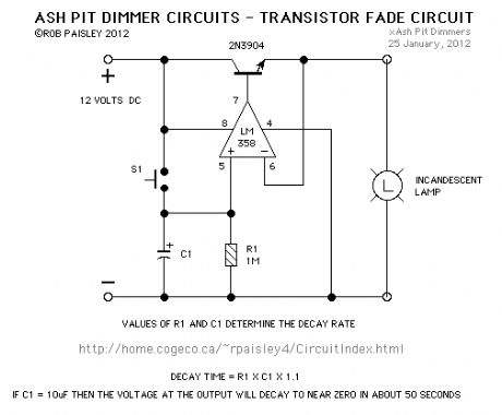
Ash Pit Dimmer Circuit
Published:2013/6/13 1:24:00 Author:muriel | Keyword: Ash Pit Dimmer Circuit
View full Circuit Diagram | Comments | Reading(962)
DCC Booster Anti-Fault Transistion Block
Published:2013/6/13 1:23:00 Author:muriel | Keyword: DCC Booster, Anti-Fault Transistion Block

View full Circuit Diagram | Comments | Reading(685)
3 Wire Output Circuit
Published:2013/6/7 21:41:00 Author:muriel | Keyword: 3 Wire , Output Circuit

View full Circuit Diagram | Comments | Reading(638)
4 Wire Output Circuit
Published:2013/6/7 21:40:00 Author:muriel | Keyword: 4 Wire, Output Circuit

View full Circuit Diagram | Comments | Reading(515)
Finding The Coil Resistance Of A Meter
Published:2013/6/7 21:40:00 Author:muriel | Keyword: The Coil Resistance , Meter

The following diagram shows a method for finding the coil resistance of a meter. Sometimes the coil resistance is marked on the meter face below the clear area of the meter's window. (View)
View full Circuit Diagram | Comments | Reading(593)
Volts and Amps Schematic
Published:2013/6/7 21:39:00 Author:muriel | Keyword: Volts and Amps Schematic

A D.P.D.T. switch and the original voltmeter calibrating resistor (Rv) could be added to the circuit allowing one meter to be used for both amps and volts. See the schematic below. (View)
View full Circuit Diagram | Comments | Reading(523)
1.5 AMP - Shunt Ammeter Circuit
Published:2013/6/7 21:39:00 Author:muriel | Keyword: 1.5 AMP, Shunt Ammeter Circuit

View full Circuit Diagram | Comments | Reading(580)
5 Times Around Circuit
Published:2013/6/7 21:36:00 Author:muriel | Keyword: 5 Times Around Circuit

The 5 Times Around circuit was designed to automatically let an N Scale locomotive and car travel around a loop 5 times and stop for approximately a minute and then repeat the cycle. The loop of track was set up as an amusement park type of ride in the trolley section of The London Model Railroad Group's, 'O' scale layout. The club is located at London, Ontario, Canada. (View)
View full Circuit Diagram | Comments | Reading(774)
ULN2003 - High voltage/High Current Peripheral Driver IC
Published:2013/6/7 21:35:00 Author:muriel | Keyword: ULN2003, High voltage, High Current, Peripheral Driver IC
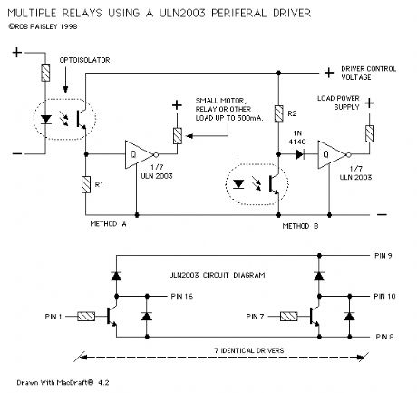
The next diagram shows an inexpensive method of building multiple medium current relays.
The circuit uses a ULN2003 - High voltage/High Current Peripheral Driver IC. This device can handle loads of 500 milliamps.
The IC is designed to have TTL and CMOS inputs of between 5 and 15 volts can be controlled by any clean input voltage. (View)
View full Circuit Diagram | Comments | Reading(1454)
Basic Solid State Relays
Published:2013/6/7 21:35:00 Author:muriel | Keyword: Basic Solid State Relays

The following are examples of home made solid state relays that could be used to replace mechanical types in many model railroad circuits.
These Relays would be ideal for applications where many relays are needed and the load current requirements are low. Due to their small size a large number of relays could be mounted on a single printed circuit board.
The relays are based on a 4N33 Optoisolator package. This device has a Darlington output transistor and as the first figure shows it can be used alone for low power applications of up to 30Ma. The second figure shows a version for higher current loads of up to 250Ma. (View)
View full Circuit Diagram | Comments | Reading(1109)
The "MoAT" Project Throttle.
Published:2013/6/7 21:34:00 Author:muriel | Keyword: The "MoAT" Project Throttle.

The third schematic is a throttle that was built for the London Model Railroad Group because of a quest for more power (amps) to triple head an all brass 21 hopper coal drag with scratch built Steam locomotives.
A quest ranking somewhere between that for the Holy Grail and the Golden Fleece. The fact that the transformer (22 Volts and 15 Amps) that powers this throttle just happened to appear at the right time helped get it off the ground.
As the schematic shows this design uses two silicon controlled rectifiers that are triggered through a special SCR trigger transformer. This transformer allows the cathodes and gates of the SCR's to be isolated from the control circuit and thus permitting the incorporation of the over current protection into the throttle.
The SCR's form half of a rectifier bridge that provides the track power while the two diodes in the bridge module that the SCR's replace supply power only to the PUJT and the control circuits. In effect the power flow through each SCR's is halved because each is triggered on every other cycle of the full wave DC.
The current limiting simply bleeds the charge off of the memory capacitor if the voltage across the 0.05 ohm resistor rises higher than the voltage at the plus input of Ic2. The voltage across this resistor is directly proportional to the current through it (E = I X R). The level of limiting is adjusted by the 10K ohm potentiometer. (View)
View full Circuit Diagram | Comments | Reading(966)
| Pages:97/2234 At 2081828384858687888990919293949596979899100Under 20 |
Circuit Categories
power supply circuit
Amplifier Circuit
Basic Circuit
LED and Light Circuit
Sensor Circuit
Signal Processing
Electrical Equipment Circuit
Control Circuit
Remote Control Circuit
A/D-D/A Converter Circuit
Audio Circuit
Measuring and Test Circuit
Communication Circuit
Computer-Related Circuit
555 Circuit
Automotive Circuit
Repairing Circuit