
Circuit Diagram
Index 96
Full Wave Rectification of DCC Voltages
Published:2013/6/13 21:23:00 Author:muriel | Keyword: Full Wave Rectification , DCC Voltages

The next diagram shows the effect of rectifying a DCC voltage with a full wave bridge. The voltage at the output of the bridge is equal to the input minus the drop across the diodes.
The small tick in the output of the bridge occurs when the polarity of the H-Bridge reverses. The size of the ticks is largely determined by the efficiencies of the H-Bridge and rectifier bridge and in most cases can be ignored. This is why filter capacitors are not needed for decoders.
Diodes used to rectify DCC should be Schottky or high speed silicon types. Diodes of the 1N4000 and 1N5400 series are not suitable for this application due to their slow turn-off times. (View)
View full Circuit Diagram | Comments | Reading(813)
DCC To DC - Accessory Power Supplies
Published:2013/6/13 21:22:00 Author:muriel | Keyword: DCC To DC , Accessory Power Supplies
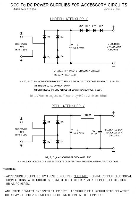
These circuits can be used to supply low current DC accessory circuits by tapping into the DCC track supply Bus. This might be done if a regular DC supply was not available and the power required by the accessory was small.
The unregulated power supply circuit could be used to supply power to the Automatic Grade Crossing circuit on this site.
WARNING - Accessories supplied by these circuits must not share common electrical connections with circuits connected to other power supplies, either DCC or AC powered. Any inter-connections with other circuits should be through optoisolators or relays to prevent possible short-circuiting between the supplies. (View)
View full Circuit Diagram | Comments | Reading(1087)
Adding External Meters to DC Throttles
Published:2013/6/13 21:21:00 Author:muriel | Keyword: Adding External Meters, DC Throttles

Typical analog meters must be added before the reversing switch. 'Centre zero' meters can be connected after the reversing switch.
Digital meters could easily be added to the output of a DC throttle so that they indicate, volts, current and polarity of the output.
Many digital multimeters are less expensive than analog meters and often easier to find locallys.
Each digital meter must have its own battery or short circuits/sneak current paths will be created between the meters wich could dammage the meters or give false readings.
The battery for the digital multimeters could also be switched by an optoisolator powered from the pack's auxiliary output so that the meters are turned off when the thottle is off.
(View)
View full Circuit Diagram | Comments | Reading(575)
LM311 Tehermostat Circuits
Published:2013/6/13 21:21:00 Author:muriel | Keyword: LM311, Tehermostat Circuits

View full Circuit Diagram | Comments | Reading(1668)
5 Second Ramp Generator for Locomotive Sound Card Demonstration
Published:2013/6/13 21:20:00 Author:muriel | Keyword: 5 Second, Ramp Generator , Locomotive Sound, Card Demonstration

The circuit on this page is designed to produce a timed throttle output for demonstrating on board sound systems in a large scale locomotive.
When a push button is activated the output will rise from 0 to 15 volts in 5 seconds. The voltage will then hold for 5 seconds. The voltage will then return to 0 in about 10 seconds.
When S1 is pushed the 555 timer will start and run for 10 seconds.
For the first 5 seconds the 10 uF capacitor at the PLUS input of the LM 358 or LM324 OPAMP will charge until it reaches the voltage at pin 5 of the 555 timer chip plus 0.7 volts
The voltage across the capacitor will now be steady for 5 seconds.
When the timer shuts off the voltage across the capacitor will decay to 0 over a period of 10 seconds, 5 seconds if the optional diode and resistor are used.
The output of the OPAMP drives a conventional transistor throttle output section.
Notes
The 500K ohm variable resistors are used to adjust the charging rate so that the capacitor at the PLUS input of the OPAMP reaches it maximum voltage (2/3 of the supply - plus 0.7 volts) in 1/2 of the timers output duration. This control could be replaced by a fixed resistor once the required value is determined.
The circuit is designed to produce an output of15 Volts when operated from a well filtered or regulated 20 Volt power supply only. If voltage adjustment is required the value of the 13K ohm resistor can be increased to give a lower output voltage or it can be decreased to give a higher output voltage.
This circuit has no automatic current limiting or overload protection. With a proper supply the circuit will deliver about 2 amps.
A heat sink may be needed for the output transistor.
The parts values shown on the schematic drawing are calculated to give the desired times and output voltages. Due to value tolerances of all of the parts and the leakage currents of the capacitors some adjustment may be required to achieve the desired results. (View)
View full Circuit Diagram | Comments | Reading(1081)
Back And Forth - Bipolar Stepper Motor Driver
Published:2013/6/13 21:19:00 Author:muriel | Keyword: Back And Forth , Bipolar Stepper, Motor Driver

View full Circuit Diagram | Comments | Reading(2408)
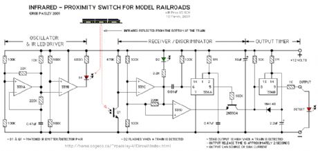
Model Railroad - Infrared Proximity Switch
Published:2013/6/13 21:18:00 Author:muriel | Keyword: Model Railroad , Infrared Proximity Switch
View full Circuit Diagram | Comments | Reading(1188)
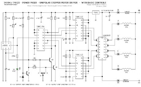
Stepper Motor Driver (74194)
Published:2013/6/13 21:18:00 Author:muriel | Keyword: Stepper Motor Driver , 74194
View full Circuit Diagram | Comments | Reading(2801)
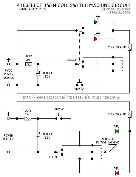
Preselect Twin Coil Switch Machine Circuit
Published:2013/6/13 21:17:00 Author:muriel | Keyword: Preselect Twin Coil, Switch Machine Circuit
View full Circuit Diagram | Comments | Reading(834)
N.O. Magnetic Reed Switch ON /OFF Circuit
Published:2013/6/13 21:16:00 Author:muriel | Keyword: N.O. Magnetic Reed, Switch, ON /OFF Circuit
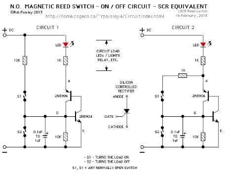
View full Circuit Diagram | Comments | Reading(1455)
Team digital - SCR16 - Twin Coil Switch Machine Adapter
Published:2013/6/13 21:16:00 Author:muriel | Keyword: Team digital , SCR16 , Twin Coil , Switch Machine Adapter

View full Circuit Diagram | Comments | Reading(809)
PIR Video Camera Control
Published:2013/6/13 1:43:00 Author:muriel | Keyword: PIR Video Camera Control

View full Circuit Diagram | Comments | Reading(907)
PUJT & Voltage Comparator - Power On - Delay Circuits
Published:2013/6/13 1:42:00 Author:muriel | Keyword: PUJT, Voltage Comparator , Power On - Delay Circuits
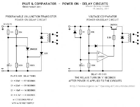
View full Circuit Diagram | Comments | Reading(1245)
High Current Switch Machine Motor Driver
Published:2013/6/13 1:41:00 Author:muriel | Keyword: High Current, Switch Machine , Motor Driver

View full Circuit Diagram | Comments | Reading(865)
3 Position Servo Driver Circuit (LM555)
Published:2013/6/13 1:41:00 Author:muriel | Keyword: 3 Position , Servo Driver Circuit, LM555

View full Circuit Diagram | Comments | Reading(1801)
Servo Motor Test Circuit (LM555)
Published:2013/6/13 1:40:00 Author:muriel | Keyword: Servo Motor, Test Circuit , LM555

View full Circuit Diagram | Comments | Reading(2233)
Transistor Based Current Regulators
Published:2013/6/13 1:39:00 Author:muriel | Keyword: Transistor , Based Current Regulators

View full Circuit Diagram | Comments | Reading(1243)
LM317 Current Regulator
Published:2013/6/13 1:39:00 Author:muriel | Keyword: LM317, Current Regulator

The following is a current regulator built around the LM317 voltage regulator IC. For additional information, see the datasheet for the LM317 series regulators.
(View)
View full Circuit Diagram | Comments | Reading(1228)
Diode Type Constant Lighting Circuits
Published:2013/6/13 1:37:00 Author:muriel | Keyword: Diode Type, Constant Lighting Circuits

View full Circuit Diagram | Comments | Reading(838)
Low Voltage Power Supplies For LEDs Or Lamps
Published:2013/6/13 1:37:00 Author:muriel | Keyword: Low Voltage, Power Supplies, LEDs , Lamps
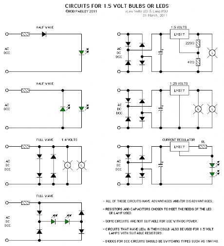
View full Circuit Diagram | Comments | Reading(1016)
| Pages:96/2234 At 2081828384858687888990919293949596979899100Under 20 |
Circuit Categories
power supply circuit
Amplifier Circuit
Basic Circuit
LED and Light Circuit
Sensor Circuit
Signal Processing
Electrical Equipment Circuit
Control Circuit
Remote Control Circuit
A/D-D/A Converter Circuit
Audio Circuit
Measuring and Test Circuit
Communication Circuit
Computer-Related Circuit
555 Circuit
Automotive Circuit
Repairing Circuit