
Circuit Diagram
Index 85
SmartCap circuitry
Published:2013/7/3 2:26:00 Author:muriel | Keyword: SmartCap circuitry

View full Circuit Diagram | Comments | Reading(539)
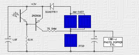
SmartCap solar engine
Published:2013/7/3 2:25:00 Author:muriel | Keyword: SmartCap solar engine
View full Circuit Diagram | Comments | Reading(1299)
SIMD1 / Solar Regulator
Published:2013/7/3 2:25:00 Author:muriel | Keyword: SIMD1, Solar Regulator

The SIMD1 was enhanced in the Solar Regulator version which supplies a constant 2V after triggering and permits driving LEDs without using current limiting resistors with constant brightness. Note that you can use this Low Drop Out (LDO) linear regulator for various applications but like all linear regulators it is lossy . This is not a problem for controlling LEDs since they would otherwise use lossy resistors but for motors it is a different story.
Try this new SIMD1 / Solar Voltage Regulator for use with blinking LED circuits (pummers). It turns on when it gets dark, just like a D1 but the output voltage is regulated to about 2V (depending on the reference LED Vf).
The SIMD1 / solar regulator circuit draws no current during charging and when turned on, it draws less than 100uA with a maximum 10ma output current. The regulator provides constant LED brightness during the discharge and turns off when 1F solar capacitor voltage drops below the LED turn on voltage. The LED used for voltage reference in the solar regulator feedback loop and the LEDs used for the flasher must be the same high efficiency type to match the forward voltage specs. This circuit is ideal for supplying voltage to a Bicore or 74HC14 LED flasher since it eliminates the LED current limiting resistors and greatly reduces current consumption of the HC flasher circuits.
(View)
View full Circuit Diagram | Comments | Reading(660)
SIMD1 V3
Published:2013/7/3 2:24:00 Author:muriel | Keyword: SIMD1 V3

View full Circuit Diagram | Comments | Reading(587)
SIMD1 V2 Example Circuit 2
Published:2013/7/3 2:24:00 Author:muriel | Keyword: SIMD1 V2 Example Circuit 2

View full Circuit Diagram | Comments | Reading(560)
SIMD1 V2 Basic Circuit (PNP)
Published:2013/7/3 2:24:00 Author:muriel | Keyword: SIMD1 V2 Basic Circuit (PNP)

View full Circuit Diagram | Comments | Reading(553)
SIMD1 V2 Example Circuit
Published:2013/7/3 2:23:00 Author:muriel | Keyword: SIMD1 V2 Example Circuit

View full Circuit Diagram | Comments | Reading(576)
SIMD1 V2 Basic Circuit
Published:2013/7/3 2:23:00 Author:muriel | Keyword: SIMD1 V2 Basic Circuit

View full Circuit Diagram | Comments | Reading(478)
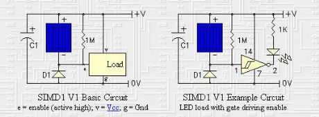
SIMD1 V1
Published:2013/7/3 2:22:00 Author:muriel | Keyword: SIMD1 V1
View full Circuit Diagram | Comments | Reading(405)
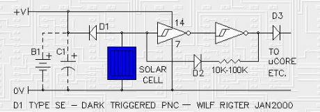
SIMD1
Published:2013/7/3 2:22:00 Author:muriel | Keyword: SIMD1
View full Circuit Diagram | Comments | Reading(438)
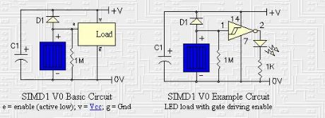
SIMD1 V0
Published:2013/7/3 2:21:00 Author:muriel | Keyword: SIMD1 V0
View full Circuit Diagram | Comments | Reading(397)
D1 solar engine
Published:2013/6/27 21:30:00 Author:muriel | Keyword: D1 solar engine
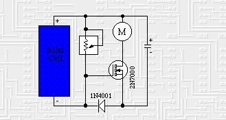
The D1 solar engine is the original nocturnal solar engine design.
The design is simple, tuneable, but no longer terribly useful (I include it here just for purposes of education and folks' historical interest). This design has a number of weaknesses; courtesy of Wilf Rigter, here are a few:
In order to turn on the FET the gate terminal needs at least +3V with respect to the source terminal and since the gate senses the difference between the solar cell voltage and the capacitor voltage it needed a relatively high charging voltage for the capacitor and a very dark solar cell to turn on and then only tolerates a small voltage drop on the cap as it discharges into the rest of the circuit before the FET turns off because the gate voltage is starved!
When the FET finally turns on in the dark, it does so slowly and for a period of time the FET is only partially on, discharging the capacitor at a low current which is not enough to do any work but nonetheless consumes stored energy. This design gives a mushy turn on point and no hysteresis and a significant amount of energy wasted in the forward voltage drop when partially turned on.
FET are not as common as other components such as 1N34 Ge diodes or 2N3904 / 2N3906 transistors available from Radio Shack.
Either the SmartCap or one of Wilf's SIMD1 (simplified D1) designs will do quite nicely at addressing these deficiencies. (View)
View full Circuit Diagram | Comments | Reading(1064)
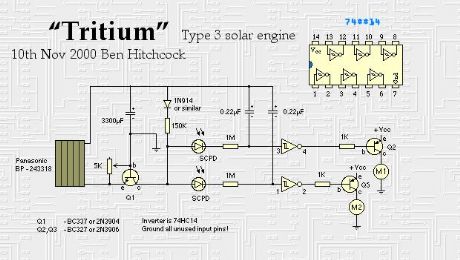
"Tritium" type 3 solar engine
Published:2013/6/27 21:29:00 Author:muriel | Keyword: "Tritium" type , 3 solar engine
View full Circuit Diagram | Comments | Reading(1512)
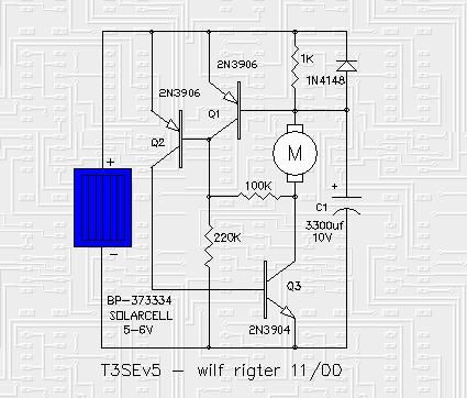
T3SE type 3 solar engine
Published:2013/6/27 21:28:00 Author:muriel | Keyword: T3SE type, 3 solar engine
View full Circuit Diagram | Comments | Reading(1235)
"Happy Birthday Singer" solar engine
Published:2013/6/27 21:28:00 Author:muriel | Keyword: "Happy Birthday Singer" solar engine
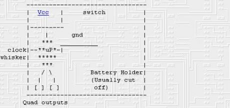
The original Type 2 Solar Engine was based around the Happy Birthday Singer (HBS) chip that was pulled from the original Hallmark singing greeting cards. While it's no longer available, this is interesting for educational as well as historical reasons. Here are the particulars as described by Mark Tilden:
The happy-birthday singer is a two bit wide by n words deep programable sequencer with 4 commands: reset to start vector (00), decrease frequency (01),increase frequency (10), and pause (11). The device starts out with a 2 word vector jump at the start of memory which locates 16 positions in it's memory. This jump vector is readdressed whenever a (11) command is found in the execution table. Happy Birthday is the first in this chain and is at default (00-00). There are at least 6 songs already in the device which can be found by reprogramming the jump vectors. The vector locations seem to be at either 256 or 512 bit increments in a 4k or 8k memory map. These songs include you light up my life , and xmas carols. Reprogramming the singers is not simple in either process or technology, and truth to tell I never completed my studies of the devices as it's a bugger working with an already burned-in prom. The only details solaroller builders need know are:
Soldering a cap between the thin clock whisker and Vcc gives an approximate ratio of 1 second period = 0.1 uF.
Device operates from 0.98 V to 5 V with a significant current drain happening around 3.1 V (approx 3 mA nominal). Device works optimally from 1.2 V to 2.3 V. A short of the power pins will reset the device but the device has a power down mode between 0.3 and 0.98 V where it will keep it's internal count position without resetting. The input impedance of the clock whisker is very high, and is obviously a direct link to the internal resistor-cap junction of the internal oscillator. This pin has the classic cap charge-discharge curve when probed. Resistors to this pin will also work, but at a significant current increase for low power applications.
Operating current of the device at 1.5 V is in the microamps with the piezo removed.
The outputs are rail to rail drivers at about 2-3 mA per transition. The outputs are quadrature encoded, so they are always opposite polarity to each other. They can be direct shorted for long periods without affecting the device and handle positive and negative current spikes well.
The only way of destroying them under nominal conditions is to power them up backwards. They die very quietly and then the only way to test is by reattaching the piezo crystal to hear if the oscillator has stopped. Another fault is when the cap soldered to the whisker is not superglued down after being attached. There is no cure for this as the whisker is usually lifted right from the pcb. Replace the device with another one.
(View)
View full Circuit Diagram | Comments | Reading(867)
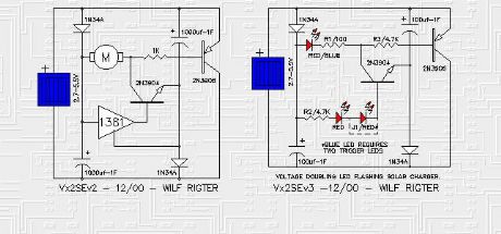
Vx2SE solar engine
Published:2013/6/27 21:27:00 Author:muriel | Keyword: Vx2SE solar engine
View full Circuit Diagram | Comments | Reading(998)
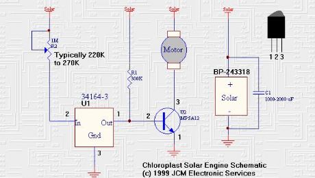
"Chloroplast" solar engines
Published:2013/6/27 21:26:00 Author:muriel | Keyword: "Chloroplast" solar engines
View full Circuit Diagram | Comments | Reading(948)
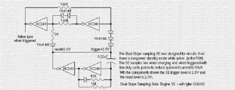
dual slope-sampling solar engine
Published:2013/6/27 21:26:00 Author:muriel | Keyword: dual , slope-sampling solar engine
View full Circuit Diagram | Comments | Reading(858)
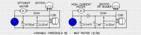
VTSE solar engine
Published:2013/6/27 21:25:00 Author:muriel | Keyword: VTSE solar engine
View full Circuit Diagram | Comments | Reading(880)
MicroPower SE 2
Published:2013/6/27 21:25:00 Author:muriel | Keyword: MicroPower SE
View full Circuit Diagram | Comments | Reading(1002)
| Pages:85/2234 At 2081828384858687888990919293949596979899100Under 20 |
Circuit Categories
power supply circuit
Amplifier Circuit
Basic Circuit
LED and Light Circuit
Sensor Circuit
Signal Processing
Electrical Equipment Circuit
Control Circuit
Remote Control Circuit
A/D-D/A Converter Circuit
Audio Circuit
Measuring and Test Circuit
Communication Circuit
Computer-Related Circuit
555 Circuit
Automotive Circuit
Repairing Circuit