
Circuit Diagram
Index 95
Special Function Timer Circuits (LM555) 2
Published:2013/6/18 3:49:00 Author:muriel | Keyword: Special Function Timer

View full Circuit Diagram | Comments | Reading(950)
Special Function Timer Circuits (LM555) 1
Published:2013/6/18 3:49:00 Author:muriel | Keyword: Special Function , Timer Circuits, LM555
View full Circuit Diagram | Comments | Reading(1038)
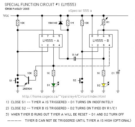
Special Function Timer Circuits (LM555)
Published:2013/6/18 3:48:00 Author:muriel | Keyword: Special, Function Timer Circuits , LM555

View full Circuit Diagram | Comments | Reading(1111)
LM 555 Photo-Detector With Delayed Release
Published:2013/6/18 3:47:00 Author:muriel | Keyword: LM 555, Photo-Detector , Delayed Release

View full Circuit Diagram | Comments | Reading(1150)
555 Photo-Detector Design Guide Sheet
Published:2013/6/18 3:47:00 Author:muriel | Keyword: 555 Photo-Detector, Design Guide Sheet

View full Circuit Diagram | Comments | Reading(1015)
Light Activated Detector Circuit
Published:2013/6/18 3:46:00 Author:muriel | Keyword: Light Activated Detector Circuit

This page shows three circuits for using the 555 timer IC as a photocell controlled train detector.
The circuit is shown driving light emitting diodes but any load of less than 200 milliamps could be used.
Shown on the schematic is a secondary output that uses the open collector at the DISCHARGE terminal (Pin 7) of the timer. This output can sink a fairly large current and would be ideal for driving relays. (View)
View full Circuit Diagram | Comments | Reading(1230)
High Side Current Monitor Specific IC
Published:2013/6/18 3:46:00 Author:muriel | Keyword: High Side , Current Monitor , Specific IC
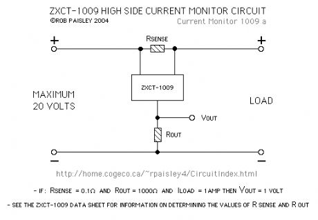
The next circuit uses an integrated circuit that is specifically designed for this application. There are a number of manufactures of these devices and there is also a considerable variety of features that can be had from specific IC's.
Due to the internal circuitry of this device, no diodes are required in the supply circuit. (View)
View full Circuit Diagram | Comments | Reading(1153)
OpAmp - High Side Current Monitor
Published:2013/6/18 3:45:00 Author:muriel | Keyword: OpAmp , High Side , Current Monitor

The first circuit is a current monitor made with an LM358 OpAmp. While functional, the three diodes in the supply line make it unsuitable for most applications.
Diodes D1, D2 and D3 are used to ensure that the voltage at the input terminals is at least two volts lower than the amplifiers supply voltage. This is undesirable as the voltage to the load is reduced and power is wasted as heat produced by the diodes.
The circuit is good for experimenting as it can be made from readily available parts. (View)
View full Circuit Diagram | Comments | Reading(2057)
Incandescent LED Circuit
Published:2013/6/18 3:44:00 Author:muriel | Keyword: Incandescent LED Circuit
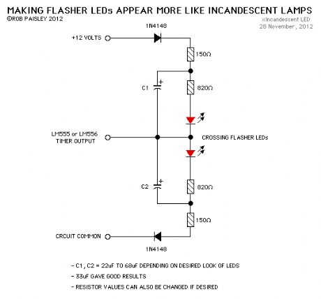
This circuit when used with a 555 timer will cause light emitting diodes to turn on and off more slowly. This will make the LEDs appear similar to incandescent lamps. (View)
View full Circuit Diagram | Comments | Reading(941)
Transformer Secondary Voltage Reduction
Published:2013/6/18 3:44:00 Author:muriel | Keyword: Transformer , Secondary Voltage Reduction

These circuits uses bridge rectifiers to reduce the secondary voltage from transformers. The current rating of the bridges should be 1.5 times the expected maximum current or greater. (View)
View full Circuit Diagram | Comments | Reading(1096)
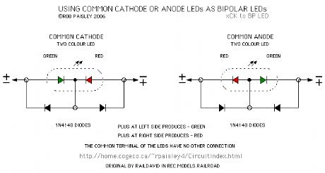
Using Common Cathode Or Anode LEDs As Bipolar LEDs
Published:2013/6/18 3:43:00 Author:muriel | Keyword: Common Cathode , Anode LEDs , Bipolar LEDs
View full Circuit Diagram | Comments | Reading(2015)
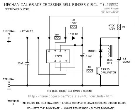
Grade Crossing Bell Ringer (LM555)
Published:2013/6/13 21:29:00 Author:muriel | Keyword: Grade Crossing Bell Ringer, LM555
View full Circuit Diagram | Comments | Reading(756)
simulate school bus flashers
Published:2013/6/13 21:28:00 Author:muriel | Keyword: simulate school bus flashers
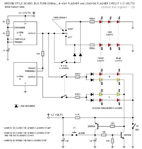
The second circuit was designed to simulate school bus flashers that are to be found in the state of Oregon. The Loading/Unloading lights flash alternately RED or YELLOW depending on whether the bus is slowing down or has stopped and the door is open. (View)
View full Circuit Diagram | Comments | Reading(1386)
School Bus Signals Circuit
Published:2013/6/13 21:27:00 Author:muriel | Keyword: School Bus Signals Circuit
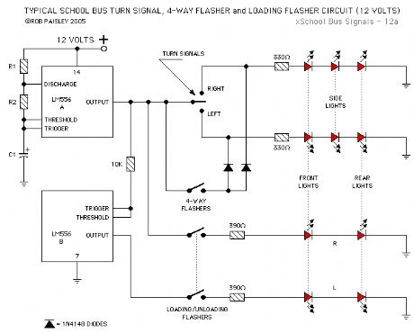
The first circuit is for school bus Loading/Unloading flashers used in most areas. (View)
View full Circuit Diagram | Comments | Reading(925)
TSOP4840 Ir Receiver Modules
Published:2013/6/13 21:26:00 Author:muriel | Keyword: TSOP4840 Ir Receiver Modules

The following diagram is for an oscillator that was used to get the information for Oscillator Output - C as shown above. (View)
View full Circuit Diagram | Comments | Reading(1425)
Ir Receiver Modules
Published:2013/6/13 21:26:00 Author:muriel | Keyword: Ir Receiver Modules

View full Circuit Diagram | Comments | Reading(2964)
Snubber Diodes Across Relay Coils
Published:2013/6/13 21:25:00 Author:muriel | Keyword: Snubber Diodes , Across Relay Coils

View full Circuit Diagram | Comments | Reading(1158)
Uncoupling Ramp Driver
Published:2013/6/13 21:24:00 Author:muriel | Keyword: Uncoupling Ramp Driver

View full Circuit Diagram | Comments | Reading(824)
10, 8 And 6 Step LED Circuits
Published:2013/6/13 21:24:00 Author:muriel | Keyword: 10, 8 And 6 Step , LED Circuits
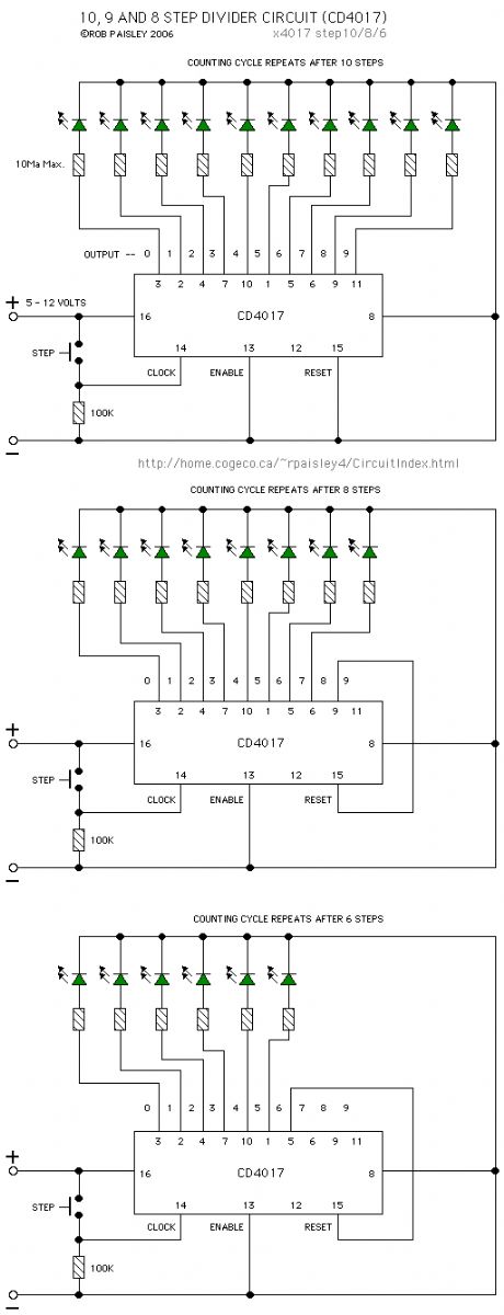
Each time switch S1 is closed the count on the CD4017 advances by 1 step and the coresponding LED turns on. When the maximium count plus 1 is reached for each circuit the cycle is restarted and repeats.
(View)
View full Circuit Diagram | Comments | Reading(1272)
Train Mounted Camera Battery Charger
Published:2013/6/13 21:23:00 Author:muriel | Keyword: Train Mounted Camera, Battery Charger
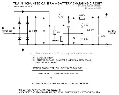
This circuit will keep the battery for a train mounted camera charged and will shut the camera off after a few seconds when power is no longer applied to the track.
The circuit is designed for DCC systems and the battery is essentially used as a capacitor as it is not allowed to become discharged.
The battery also controls the voltage to the camera as any current passed through R1 that is not needed by the camera is shunted through the battery. This is an inefficient but cheap way to control the voltage.
(View)
View full Circuit Diagram | Comments | Reading(796)
| Pages:95/2234 At 2081828384858687888990919293949596979899100Under 20 |
Circuit Categories
power supply circuit
Amplifier Circuit
Basic Circuit
LED and Light Circuit
Sensor Circuit
Signal Processing
Electrical Equipment Circuit
Control Circuit
Remote Control Circuit
A/D-D/A Converter Circuit
Audio Circuit
Measuring and Test Circuit
Communication Circuit
Computer-Related Circuit
555 Circuit
Automotive Circuit
Repairing Circuit