
Circuit Diagram
Index 94
CA4060B Timer Circuits
Published:2013/6/18 20:49:00 Author:muriel | Keyword: CA4060B, Timer Circuits

View full Circuit Diagram | Comments | Reading(985)
1 Transformer For 2 Throttles schematic
Published:2013/6/18 3:58:00 Author:muriel | Keyword: 1 Transformer, 2 Throttles schematic

View full Circuit Diagram | Comments | Reading(572)
Bi-Colour LED Output Shifting
Published:2013/6/18 3:58:00 Author:muriel | Keyword: Bi-Colour LED, Output Shifting
View full Circuit Diagram | Comments | Reading(1541)
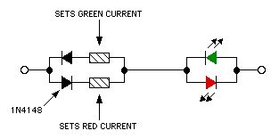
Bi-Colour LED Output Shifting Schematic
Published:2013/6/18 3:57:00 Author:muriel | Keyword: Bi-Colour LED , Output Shifting Schematic

These circuits provide a means of altering the YELLOW output of RED / GREEN type two colour light emitting diodes. These circuits use the LM555 timer chip. (View)
View full Circuit Diagram | Comments | Reading(964)
Push Button Motor Control Circuit - 3
Published:2013/6/18 3:57:00 Author:muriel | Keyword: Push Button Motor, Control Circuit

View full Circuit Diagram | Comments | Reading(1493)
Push Button Motor Control Circuit - 2
Published:2013/6/18 3:57:00 Author:muriel | Keyword: Push Button Motor , Control Circuit

View full Circuit Diagram | Comments | Reading(1872)
Push Button Motor Control Circuits
Published:2013/6/18 3:56:00 Author:muriel | Keyword: Push Button, Motor, Control Circuits
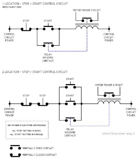
The circuits on this page are for motor controls using Push buttons and would typically be found in commercial and industrial installations.
The circuits do not show the wiring of the motors themselves as this depends on the particular motor type. The type of motor also governs the number of contacts needed for the motor side of these circuits.
The Relay Holding Contacts and the Interlock Contacts shown in these circuit would normally be built into the motor control relays. (View)
View full Circuit Diagram | Comments | Reading(2054)
DCC - Zero Stretching Simulator
Published:2013/6/18 3:55:00 Author:muriel | Keyword: DCC - Zero Stretching Simulator

This circuit is designed to simulate the 'Zero Stretching' function of Digital Command Control systems used by model railroads.
This circuit was used drive the booster while testing the operation of block occupancy detectors and DCC signal failure circuits while in the zero stretching mode.
The parts values have been calculated to give the maximum stretching length and ratio allowed for DCC systems. Complimentary outputs, A and B, are provided in order to drive the booster's output polarity stretched in both directions. (View)
View full Circuit Diagram | Comments | Reading(711)
Finding The Resistance Of Meter Coils
Published:2013/6/18 3:55:00 Author:muriel | Keyword: Resistance , Meter Coils

View full Circuit Diagram | Comments | Reading(698)
High impedance Test Voltmeter Schematic
Published:2013/6/18 3:54:00 Author:muriel | Keyword: High impedance , Test Voltmeter Schematic

View full Circuit Diagram | Comments | Reading(1603)
Connection Of Detectors
Published:2013/6/18 3:54:00 Author:muriel | Keyword: Connection, Detectors

View full Circuit Diagram | Comments | Reading(740)
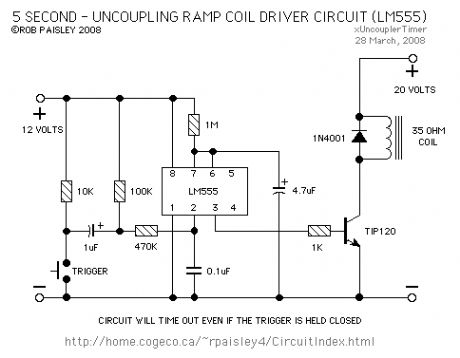
Timed Uncoupling Ramp Driver (LM555)
Published:2013/6/18 3:53:00 Author:muriel | Keyword: Timed Uncoupling Ramp Driver , LM555
View full Circuit Diagram | Comments | Reading(956)
Finding Bad Joints In Track Wiring
Published:2013/6/18 3:53:00 Author:muriel | Keyword: Bad Joints , Track Wiring


The following is a method of finding high resistances in track power circuits. The digital voltmeter is set to its lowest range and indicates the resistance in the track circuit by measuring the voltage drop in a given section of track.
The movable jumper is connected across individual blocks in turn in order to check each one. A high voltage indicates a bad connection. The jumper must have as low a resistance as possible to avoid false indications
Two versions of the circuit are shown. Both work identically except that the second limits the current to one ampere.
The tester can be connected as far back in the circuit as desired so that toggle switches are also included in the test.
The diagrams show gaps in both rails although this would not normally be the case. The test will still work and might find bad rail joiners as well.
(View)
View full Circuit Diagram | Comments | Reading(579)
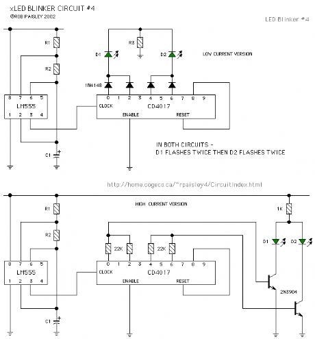
LED Blinker Circuit #4
Published:2013/6/18 3:52:00 Author:muriel | Keyword: LED Blinker Circuit
View full Circuit Diagram | Comments | Reading(983)
LED Blinker Circuit #3
Published:2013/6/18 3:51:00 Author:muriel | Keyword: LED Blinker Circuit

View full Circuit Diagram | Comments | Reading(996)
LED Blinker Circuit #2
Published:2013/6/18 3:51:00 Author:muriel | Keyword: LED Blinker Circuit

View full Circuit Diagram | Comments | Reading(774)
LED Blinker Circuit #1
Published:2013/6/18 3:51:00 Author:muriel | Keyword: LED Blinker Circuit

The circuit uses independent timers to flash two light emitting diodes. Any time that light emitting diode D1 is lit__light emitting diode D2 will be switched off. Light emitting diode D3 is on if both D1 and D2 are off.
Two versions of the circuit are shown. The second circuit uses fewer components by taking advantage of the bipolar outputs of the timers.
If the supply voltage is increased a 1N4148 diode should be placed in series with light emitting diode D3. The values of the resistors should also be increased proportionately. (View)
View full Circuit Diagram | Comments | Reading(922)
Timed DC Throttle
Published:2013/6/18 3:50:00 Author:muriel | Keyword: Timed DC Throttle

The following is a simple timed DC throttle that has controls for the length of run, accelerate/ decelerate and the maximum train speed. The circuit also has automatic current limiting.
An ideal power supply fo this circuit would be a AC wall adapter. This would likely be less expensive than building a power supply from scratch. The 7812 voltage regulator would not be needed if an adapter with a built in regulator is used.
(View)
View full Circuit Diagram | Comments | Reading(655)
Special Function Timer 4
Published:2013/6/18 3:49:00 Author:muriel | Keyword: Special Function Timer
View full Circuit Diagram | Comments | Reading(822)
Special Function Timer 3
Published:2013/6/18 3:49:00 Author:muriel | Keyword: Special Function Timer

View full Circuit Diagram | Comments | Reading(729)
| Pages:94/2234 At 2081828384858687888990919293949596979899100Under 20 |
Circuit Categories
power supply circuit
Amplifier Circuit
Basic Circuit
LED and Light Circuit
Sensor Circuit
Signal Processing
Electrical Equipment Circuit
Control Circuit
Remote Control Circuit
A/D-D/A Converter Circuit
Audio Circuit
Measuring and Test Circuit
Communication Circuit
Computer-Related Circuit
555 Circuit
Automotive Circuit
Repairing Circuit