
Circuit Diagram
Index 99
Simplified Incline Railway Control Circuit Schematic
Published:2013/6/7 21:19:00 Author:muriel | Keyword: Simplified Incline Railway, Control Circuit Schematic

IC 3 is part of the L.M.R.G. circuit and therefore was left in for this article. IC 3 can be omitted from the circuit and the mechanical contacts connected directly of the bases of Q1 and Q2 if desired. This would simplify the circuit but would not change its operation in any way. A schematic of the circuit without IC 3 follows. (View)
View full Circuit Diagram | Comments | Reading(836)
Incline Railway Control Circuit
Published:2013/6/6 21:00:00 Author:muriel | Keyword: Incline Railway, Control Circuit

View full Circuit Diagram | Comments | Reading(921)
Audible Train Approach Warning Circuit Schematic
Published:2013/6/6 20:59:00 Author:muriel | Keyword: Audible Train , Approach Warning Circuit

View full Circuit Diagram | Comments | Reading(846)
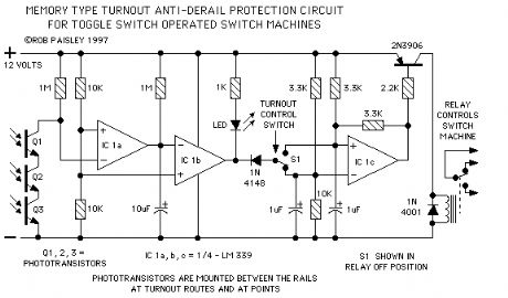
Toggle Switch Type Protection Circuit
Published:2013/6/6 20:57:00 Author:muriel | Keyword: Toggle Switch Type, Protection Circuit
View full Circuit Diagram | Comments | Reading(546)
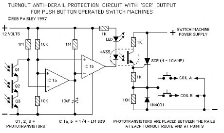
Push Button Type Protection Circuit with 'SCR' Output
Published:2013/6/6 20:56:00 Author:muriel | Keyword: Push Button Type, Protection Circuit, 'SCR' Output
View full Circuit Diagram | Comments | Reading(0)
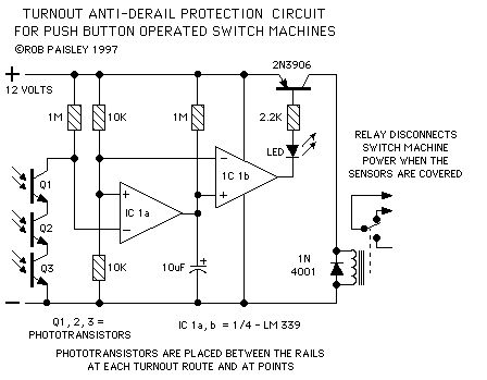
Push Button Type Protection Circuit with 'Relay' Output
Published:2013/6/6 20:56:00 Author:muriel | Keyword: Push Button Type, Protection Circuit , 'Relay' Output
View full Circuit Diagram | Comments | Reading(0)
L.M.R.G. Diamond Protection Circuit Schematic
Published:2013/6/6 20:55:00 Author:muriel | Keyword: L.M.R.G., Diamond Protection Circuit Schematic
View full Circuit Diagram | Comments | Reading(756)
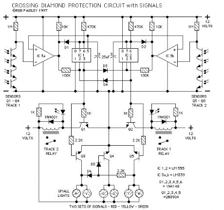
L. M. R. G. Diamond Protection Circuit
Published:2013/6/6 20:54:00 Author:muriel | Keyword: L. M. R. G., Diamond Protection Circuit
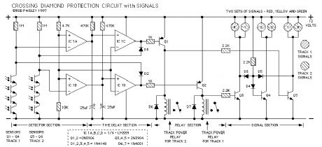
The original Crossing Diamond Protection circuit is used in several places on the London Model Railway Group's - O Scale layout. The first installation was at the main line and trolley crossing. In this location the main line cab operators cannot see a trolley approaching until it is just inches from the diamond.
The circuit shown here is a later and simpler version of the protection circuit. Included are signal lights, these are optional but do indicate who has the diamond.
(View)
View full Circuit Diagram | Comments | Reading(587)
DCC BOD - Diamond Protection Circuit
Published:2013/6/6 20:54:00 Author:muriel | Keyword: DCC BOD , Diamond Protection Circuit
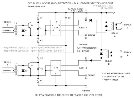
The circuit in the first schematic is for a diamond protection circuit that used two transformer type DCC Block Occupancy Detectors.
NOTE: if there is a car in the protected section but it is not drawing any current the diamond will not be protected. With photosensors, if a car is on the diamond it will be seen by the circuit at all times.
The train must have detectable cars at least at both ends and the block must be as long as the longest train. (View)
View full Circuit Diagram | Comments | Reading(885)
Day and Night Detector Circuit
Published:2013/6/6 20:53:00 Author:muriel | Keyword: Day and Night, Detector Circuit

The detector for this circuit uses a voltage comparator the same as those on the Visible and Infrared Light Detectors page at this site.
The major change is the mounting of infrared emitters mounted at ceiling height above the detectors phototransistor. (View)
View full Circuit Diagram | Comments | Reading(1030)
Model Railroad Odometer Car Schematic
Published:2013/6/6 20:51:00 Author:muriel | Keyword: Model Railroad, Odometer Car Schematic

View full Circuit Diagram | Comments | Reading(1457)
High Current - Crossing Light Flasher (LM556)
Published:2013/6/6 20:51:00 Author:muriel | Keyword: High Current , Crossing Light Flasher , LM556
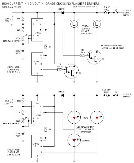
This following circuit shows a simple grade crossing flasher with enough current capacity to drive 12 Volt lamps with 2 Amps current draw. The circuit could be used for open house displays, etc.
The flasher is driven by an LM556 dual time configured in a Push-Pull arrangement.
The flash rate can be adjusted by varying the value of the 500K ohm variable resistor. The flash rate is calculated as being from 0.54 to 3.1 Hertz.
The only real concern with this circuit is the need for a 12 volt power supply large enough for the current required by the lamps. The #1156 automotive lamps specified are rated at 2.1 amps but as only one light is on at a time the current draw for the circuit would be just slightly above 2.1 amps. Other lamps such as the #1141 draw less current.
(View)
View full Circuit Diagram | Comments | Reading(1120)
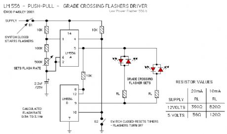
Push-Pull - Crossing Light Flasher
Published:2013/6/6 20:50:00 Author:muriel | Keyword: Push-Pull, Crossing Light Flasher
View full Circuit Diagram | Comments | Reading(966)
Synchronous Crossing Light Flashers
Published:2013/6/6 20:50:00 Author:muriel | Keyword: Synchronous Crossing Light Flashers

In the synchronous flasher control the oscillator is running at all times and the power to each set of flashers is turned on or off by the control circuit for that crossing. This allows any number of flasher sets at different crossings to controlled individually and yet flash in unison.
Two versions of the flasher output control are shown.
In OUTPUT 1 the lights are turned on when the control circuit goes to the common of the circuit.
In OUTPUT 2 the lights are turned on when the control circuit goes to the positive supply of the circuit or some other supply source.
In either case the PNP and NPN transistors above and below the LED's are turned on and the crossing lights will flash.
IF more than one set of flashers is used at a particular crossing the LED's could be wired in series so as to keep the number of output control circuits to a minimum. This is shown on the basic flasher schematic.
(View)
View full Circuit Diagram | Comments | Reading(943)
Basic Crossing Light Flasher
Published:2013/6/6 20:49:00 Author:muriel | Keyword: Basic Crossing Light Flasher

View full Circuit Diagram | Comments | Reading(868)
4 - Infrared Detectors Schematic
Published:2013/6/6 20:48:00 Author:muriel | Keyword: 4 , Infrared Detectors Schematic

The schematic shows how the LM339 can be used to build a multiple detector unit.
In order to reduce on the total current needed for the circuit the infrared LED's can be wired in series and the value of the series resistor adjusted to supply the needed current. In this way the LED's use the same 17 milliamps instead of needing 17 milliamps each.
The parts values shown on the schematic are guidelines that should work in most situations but may have to be adjusted for your particular needs.
(View)
View full Circuit Diagram | Comments | Reading(1110)
Long Range - Across The Track Infrared Detectors
Published:2013/6/6 20:47:00 Author:muriel | Keyword: Long Range, Track Infrared Detectors

The method shown below has been tested with sensor gaps as wide as 12 inches but a distance of 8 inches or less is more practical.
There is also a method that can be used for longer range across track detection that could be used for yard throats. A detector circuit of this type is in use at the London Model Railroad Group's club layout and spans seven O Scale tracks using one infrared LED and a lensed phototransistor.
(View)
View full Circuit Diagram | Comments | Reading(813)
Basic Infrared Detector Schematic
Published:2013/6/6 20:47:00 Author:muriel | Keyword: Basic Infrared, Detector Schematic
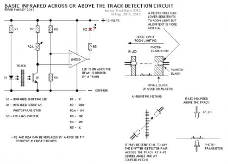
This page presents information on infrared - Above The Track and Across The Track train position detection circuits. The circuits are designed around the LM339 quad comparator chip and can use a wide assortment of matched infrared - emitter / detector pairs.
The circuit bellow is the basic voltage comparator based detector circuit using the LM339 Quad or LM393 Dual comparator ICs.
The LED will turn on when the infrared beam is broken. The value of the resistor R1 determines the sensitivity of the phototransistor Q1. In most cases a value of 1 Meg or 470K ohm with good results but every situation is different and some experimentation might be needed.
Circuit Operation - When a train breaks the infrared beam the phototransistor will conduct less current. The voltage at the MINUS input of the comparator will rise above the reference voltage at the PLUS as determined by R3 and R4. The output of the comparator to turn ON and the LED will be lit. (View)
View full Circuit Diagram | Comments | Reading(1246)
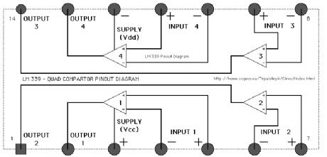
LM339- quad compartor pinput diagram 2
Published:2013/6/6 20:46:00 Author:muriel | Keyword: LM339, quad compartor , pinput diagram
View full Circuit Diagram | Comments | Reading(834)
LM339- quad compartor pinput diagram
Published:2013/6/6 20:45:00 Author:muriel | Keyword: LM339, quad compartor, pinput diagram
View full Circuit Diagram | Comments | Reading(876)
| Pages:99/2234 At 2081828384858687888990919293949596979899100Under 20 |
Circuit Categories
power supply circuit
Amplifier Circuit
Basic Circuit
LED and Light Circuit
Sensor Circuit
Signal Processing
Electrical Equipment Circuit
Control Circuit
Remote Control Circuit
A/D-D/A Converter Circuit
Audio Circuit
Measuring and Test Circuit
Communication Circuit
Computer-Related Circuit
555 Circuit
Automotive Circuit
Repairing Circuit