
Circuit Diagram
Index 90
High Current Crossing Flasher Schematic
Published:2013/6/25 21:44:00 Author:muriel | Keyword: High Current, Crossing Flasher Schematic

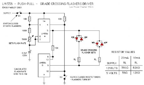
This following circuit shows a simple grade crossing flasher with enough current capacity to drive 12 Volt lamps with 2 Amps current draw. The circuit could be used for open house displays, etc.
The flasher is driven by an LM556 dual time configured in a Push-Pull arrangement.
The flash rate can be adjusted by varying the value of the 500K ohm variable resistor. The flash rate is calculated as being from 0.54 to 3.1 Hertz.
The only real concern with this circuit is the need for a 12 volt power supply large enough for the current required by the lamps. The #1156 automotive lamps specified are rated at 2.1 amps but as only one light is on at a time the current draw for the circuit would be just slightly above 2.1 amps. Other lamps such as the #1141 draw less current. (View)
View full Circuit Diagram | Comments | Reading(996)
Crossing Light Flasher
Published:2013/6/25 21:43:00 Author:muriel | Keyword: Crossing Light Flasher
The next circuit uses a dual timer in a Push-Pull output arrangement. While this circuit would be sightly more expensive to build, it would make the wiring of the actual flasher mount simpler as only two connections would be needed.The flashers can be turned on and off by using S1 to control the power to the circuit or by using S2 to RESET the timers. Resetting the timers will make both their outputs go to a LOW state. (View)
View full Circuit Diagram | Comments | Reading(992)
Synchronous Flasher Control Schematic
Published:2013/6/25 21:42:00 Author:muriel | Keyword: Synchronous Flasher Control Schematic

In the synchronous flasher control the oscillator is running at all times and the power to each set of flashers is turned on or off by the control circuit for that crossing. This allows any number of flasher sets at different crossings to controlled individually and yet flash in unison.
Two versions of the flasher output control are shown.
In OUTPUT 1 the lights are turned on when the control circuit goes to the common of the circuit.
In OUTPUT 2 the lights are turned on when the control circuit goes to the positive supply of the circuit or some other supply source.
In either case the PNP and NPN transistors above and below the LED's are turned on and the crossing lights will flash.
IF more than one set of flashers is used at a particular crossing the LED's could be wired in series so as to keep the number of output control circuits to a minimum. This is shown on the basic flasher schematic. (View)
View full Circuit Diagram | Comments | Reading(978)
Low Power Crossing Light Flashers
Published:2013/6/25 21:42:00 Author:muriel | Keyword: Low Power, Crossing Light Flashers
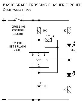
The first circuit is a basic version that can be used in many situations. (View)
View full Circuit Diagram | Comments | Reading(975)
Long Range - Across The Track Detection
Published:2013/6/25 21:41:00 Author:muriel | Keyword: Long Range, Track Detection
View full Circuit Diagram | Comments | Reading(768)
4 - Infrared Detectors
Published:2013/6/25 21:40:00 Author:muriel | Keyword: 4 - Infrared Detectors
View full Circuit Diagram | Comments | Reading(508)
Track Infrared Detectors
Published:2013/6/25 21:39:00 Author:muriel | Keyword: Track Infrared Detectors

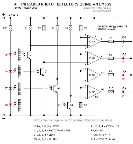
This page presents information on infrared - Above The Track and Across The Track train position detection circuits. The circuits are designed around the LM339 quad comparator chip and can use a wide assortment of matched infrared - emitter / detector pairs.
The circuit bellow is the basic voltage comparator based detector circuit using the LM339 Quad or LM393 Dual comparator ICs.
The LED will turn on when the infrared beam is broken. The value of the resistor R1 determines the sensitivity of the phototransistor Q1. In most cases a value of 1 Meg or 470K ohm with good results but every situation is different and some experimentation might be needed.
Circuit Operation - When a train breaks the infrared beam the phototransistor will conduct less current. The voltage at the MINUS input of the comparator will rise above the reference voltage at the PLUS as determined by R3 and R4. The output of the comparator to turn ON and the LED will be lit. (View)
View full Circuit Diagram | Comments | Reading(1124)
Pinout Diagrams 3
Published:2013/6/25 21:38:00 Author:muriel | Keyword: Pinout Diagrams
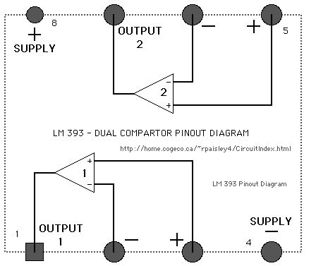
View full Circuit Diagram | Comments | Reading(671)
Pinout Diagrams 2
Published:2013/6/25 21:38:00 Author:muriel | Keyword: Pinout Diagrams
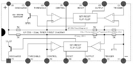
View full Circuit Diagram | Comments | Reading(667)
Pinout Diagrams
Published:2013/6/25 21:37:00 Author:muriel | Keyword: Pinout Diagrams
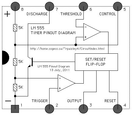
View full Circuit Diagram | Comments | Reading(798)
Using Multiple Phototransistors
Published:2013/6/24 21:46:00 Author:muriel | Keyword: Using Multiple Phototransistors
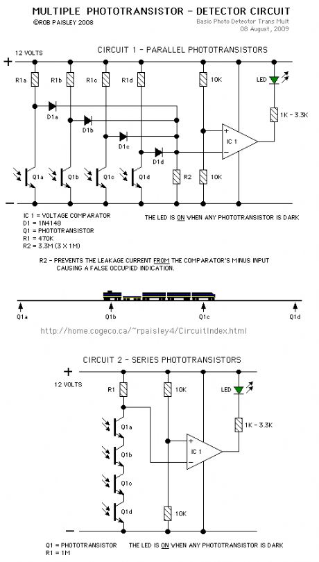
More than one phototransitor can be connected to a single voltage comparator. This would allow transistors to be placed along a section of track to indicate when a train is anywhere in that section.
As long as the train is long enough to cover two sensors the circuit will continuously detect the train.
(View)
View full Circuit Diagram | Comments | Reading(794)
Basic Photocell Detector
Published:2013/6/21 3:16:00 Author:muriel | Keyword: Basic Photocell Detector
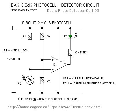
View full Circuit Diagram | Comments | Reading(894)
Basic Phototransistor Detector
Published:2013/6/21 3:16:00 Author:muriel | Keyword: Basic Phototransistor Detector
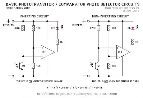
In this circuit, when the light falling on the phototransistor (Q1) is blocked, its conductance will decrease and the voltage across Q1 will rise. When the voltage rises above 1/2 of the supply voltage the output of the comparator will turn ON and the LED will be lit.The only critical part of this circuit is the value of resistor R1 which in most cases can be 470K ohms but may have to be increase if the room is dark or decreased if the room is well lit.
Increasing the value of R1 will cause the sensitivity of the sensor to decrease. This may be necessary when the light falling on the cell is not very strong or shadows can affect the phototransistor.
There are a number of phototransistors sizes and case styles. The smaller cases will be easier to hide but connecting wires may be more difficult. (View)
View full Circuit Diagram | Comments | Reading(1306)
Higher Current Motors
Published:2013/6/21 3:14:00 Author:muriel | Keyword: Higher Current Motors

View full Circuit Diagram | Comments | Reading(549)
Single-Step Input
Published:2013/6/21 3:13:00 Author:muriel | Keyword: Single-Step Input
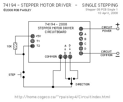
View full Circuit Diagram | Comments | Reading(756)
Basic Stepper Motor Driver
Published:2013/6/21 3:12:00 Author:muriel | Keyword: Basic Stepper Motor Driver
View full Circuit Diagram | Comments | Reading(953)
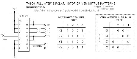
BIPOLAR Stepper Motor Driver
Published:2013/6/21 3:12:00 Author:muriel | Keyword: BIPOLAR Stepper Motor Driver

View full Circuit Diagram | Comments | Reading(1569)
basic laser pointer circuit
Published:2013/6/21 3:10:00 Author:muriel | Keyword: basic laser pointer circuit
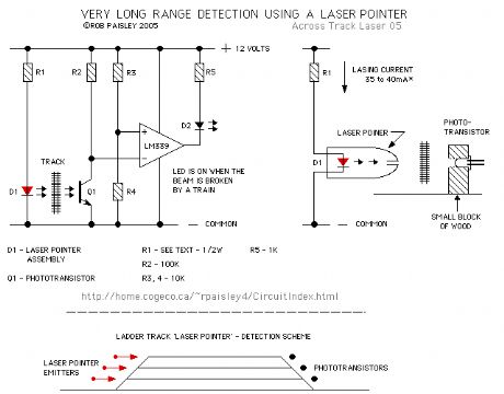
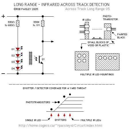
The following diagram shows the basic laser pointer circuit. It is identical to the infrared circuit except that the infrared LED's have been replaced by the laser pointer unit.
Due to the long range of these devices this detector method can easily span great distances and could be used to detect trains in a long section of straight track such as in a lader yard or across the throat of a very wide yard. (View)
View full Circuit Diagram | Comments | Reading(1374)
Basic Diode Matrix System
Published:2013/6/21 3:06:00 Author:muriel | Keyword: Basic Diode Matrix System
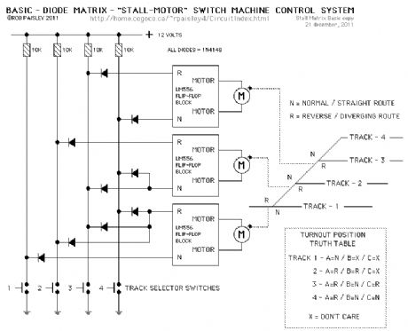
The next diagram is for a basic diode matrix system that will operate the switch machines for one end of a four track ladder yard.
Tracks 1 through 4 are selected with the appropriate push buttons. This in turn SET's or RESET's, through the diode matrix, the appropriate switch machine motor controller to its N or R condition and operates the turnouts.Included in the diagram is a Truth Table that shows the position of each turnout for the particular track that is selected. The X or DON'T CARE symbol means that it does not matter where that turnout is lined to if track 1 or 2 is selected. (View)
View full Circuit Diagram | Comments | Reading(1015)
Typical 556 Stall-Motor Driver schematic
Published:2013/6/21 3:06:00 Author:muriel | Keyword: 556 , Stall-Motor, Driver schematic
View full Circuit Diagram | Comments | Reading(765)
| Pages:90/2234 At 2081828384858687888990919293949596979899100Under 20 |
Circuit Categories
power supply circuit
Amplifier Circuit
Basic Circuit
LED and Light Circuit
Sensor Circuit
Signal Processing
Electrical Equipment Circuit
Control Circuit
Remote Control Circuit
A/D-D/A Converter Circuit
Audio Circuit
Measuring and Test Circuit
Communication Circuit
Computer-Related Circuit
555 Circuit
Automotive Circuit
Repairing Circuit