Basic Circuit
Basic Diode Matrix System
Published:2013/6/21 3:06:00 Author:muriel | Keyword: Basic Diode Matrix System | From:SeekIC

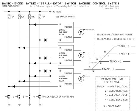
The next diagram is for a basic diode matrix system that will operate the switch machines for one end of a four track ladder yard.
Tracks 1 through 4 are selected with the appropriate push buttons. This in turn SET's or RESET's, through the diode matrix, the appropriate switch machine motor controller to its N or R condition and operates the turnouts.Included in the diagram is a Truth Table that shows the position of each turnout for the particular track that is selected. The X or DON'T CARE symbol means that it does not matter where that turnout is lined to if track 1 or 2 is selected.
Reprinted Url Of This Article:
http://www.seekic.com/circuit_diagram/Basic_Circuit/Basic_Diode_Matrix_System.html
Print this Page | Comments | Reading(3)

Article Categories
power supply circuit
Amplifier Circuit
Basic Circuit
LED and Light Circuit
Sensor Circuit
Signal Processing
Electrical Equipment Circuit
Control Circuit
Remote Control Circuit
A/D-D/A Converter Circuit
Audio Circuit
Measuring and Test Circuit
Communication Circuit
Computer-Related Circuit
555 Circuit
Automotive Circuit
Repairing Circuit
Code: